Introduction
Steam flow meter installation requires technical knowledge of steam systems, precise alignment, and careful attention to steam quality. Industry data shows that improper installation causes over one-third of all flow meter problems.
Installation errors degrade accuracy by 8-10% on average. In severe cases, incorrect installation can lead to measurement errors of 10-30%, equipment damage, and serious safety risks.
Given these risks, installation should be performed by trained technicians or engineers familiar with steam systems and flow measurement principles. Complex installations—particularly those involving differential pressure meters, high-pressure systems, or critical custody transfer applications—require manufacturer-certified specialists with steam metering expertise and hazardous area qualifications.
This guide covers complete installation from site preparation through validation, following industry best practices including ASME B31.1, ISO 5167, and manufacturer standards. Proper installation ensures measurement accuracy, equipment longevity, and safe operation across the full range of steam applications.
TLDR
- Dry steam (>80-95% dryness fraction) and proper straight pipe runs (10-25D upstream, 5-10D downstream) prevent measurement errors
- High-efficiency steam separators, Y-strainers (100-mesh minimum), and full-bore isolation valves are mandatory prerequisites
- Avoid installation directly after pressure reducing valves or sharp bends to ensure accurate readings
- Post-installation validation confirms zero leaks, proper steam quality (within 5-10°F saturation temperature), and accurate baselines
- Most installation failures stem from wet steam, insufficient straight pipe length, or improper impulse tap positioning (never at 12 or 6 o'clock)
Prerequisites and Safety Considerations for Steam Flow Meters
Site Readiness and Piping Requirements
Site preparation begins with verifying adequate straight pipe runs. Requirements vary by meter type and upstream disturbances: orifice plates typically need 10-54 pipe diameters (D) upstream depending on beta ratio and disturbance configuration, while vortex meters require 10-20D upstream.
Downstream requirements are generally 5-10D. Conditioning orifice plates can reduce these requirements to as little as 2D upstream and 2D downstream in space-constrained installations.
Pipe support must prevent misalignment and vibration that can degrade accuracy. Key installation considerations:
- Install supports at intervals specified by ASME B31.1
- Ensure meter body remains perfectly aligned with pipe centerline
- Provide 24-36 inches clearance on all sides for maintenance access
Compatibility and Safety Margins
Verify meter pressure and temperature ratings match your operating conditions. ASME B31.1 requires components to be designed for the maximum sustained operating pressure and temperature of the source, not an arbitrary percentage margin. Select instruments with Maximum Allowable Working Pressure (MAWP) ratings that exceed your system's safety valve set pressure.
Confirm pipe size matches meter specifications. If size reduction is necessary, use eccentric reducers (not concentric) with the flat side positioned at the top to prevent condensate pooling. Maintain required straight pipe distances after any reducer.
Material compatibility is critical. MAC Instruments steam flow meters feature **300 series stainless steel construction** suitable for most steam applications, providing excellent corrosion resistance and durability for pressures up to 150 PSIG.
With materials verified, proper safety protocols ensure secure installation.
Safety Requirements and Lockout/Tagout
Install full-bore isolation valves upstream and downstream to enable safe maintenance. Valves must withstand the piping design pressure and temperature per ASME B31.1 Section 122.3.2(B). Establish lockout/tagout procedures before beginning installation work.
Personal protective equipment for high-temperature steam work includes:
- Heat-resistant gloves rated for steam temperatures
- Face shields for flange work
- Insulated tools
- Fire-resistant clothing
Comply with ASME B31.1 or equivalent steam piping codes throughout installation. Instrument takeoff connections must be "lagged in with the steam main" (insulated together with the main pipe) to prevent thermal shock.
Steam Quality Prerequisites
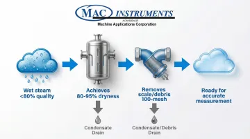
Steam quality directly impacts measurement accuracy. ISO 5167 applies only to single-phase flow. Wet steam (quality <100%) causes differential pressure and vortex meters to over-read significantly because liquid droplets create higher differential pressure than dry gas alone.
Install a high-efficiency separator upstream to achieve minimum 80-95% steam dryness fraction. Below 80% quality, condensate drops out of suspension, causing severe measurement errors. Fit a Y-strainer (100-mesh minimum) downstream of the separator to remove scale and debris that can erode meter internals.
Provide condensate drain points with properly sized steam traps at all low points in the piping. Condensate accumulation leads to water hammer, which can shatter sensor bodies and damage electronics.
Non-Negotiables: When Installation Must Not Proceed
Do not proceed with installation if any condition exists:
- Wet steam conditions exceeding meter specifications
- Insufficient straight pipe to meet manufacturer minimums
- Inadequate pressure or temperature rating for operating conditions
- Presence of severe water hammer
- Inability to fully isolate and depressurize the system
Installation Guide for Steam Flow Meters
Proper installation follows a defined sequence—preparation, mounting, integration, and configuration. Shortcuts or sequence violations commonly cause long-term accuracy issues and premature failure. Each step builds on the previous one, and skipping steps compromises the entire installation.
Preparing the Installation Site and Steam System
System Isolation and Verification:
Fully isolate, depressurize, and cool the system before beginning work. Confirm lockout/tagout procedures are in place with tags visible at all isolation points. Test for zero pressure using a calibrated gauge before opening any connections—never rely solely on visual indicators.
Allow sufficient cooling time for safe handling. Steam systems retain heat for hours after shutdown. Check that pipe surface temperature is below 120°F before removing flanges or fittings.
Pipe Interior Inspection and Cleaning:
Inspect pipe interior for scale, rust, or debris accumulation. Steam systems often contain mill scale, weld slag, and corrosion products that can damage meters. Clean pipes thoroughly if contamination is present.
Confirm the separator and strainer are installed and functioning correctly upstream. Check separator drain trap operation and strainer basket condition. Replace strainer elements if clogged or damaged.
Reducer Installation (If Required):
If meter size is smaller than pipe size, install eccentric reducers with the flat side at top.
This orientation prevents condensate from pooling at the reducer outlet, which would create turbulent flow and measurement errors. Concentric reducers trap condensate and must not be used.
Maintain required straight pipe distances after reducers. The straight run requirement begins at the reducer outlet, not at the upstream disturbance.
Positioning and Securing the Flow Meter
Flow Direction and Body Orientation:
Install the meter in the correct flow direction following the arrow marking on the body. Flow direction is critical—reversed installation causes complete measurement failure in most technologies.
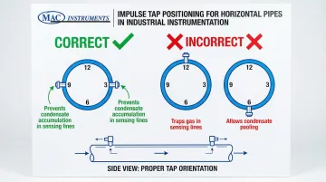
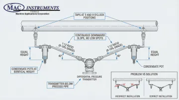
For horizontal pipe installations, position the meter body horizontally with impulse taps (for DP meters) at the 3 o'clock and 9 o'clock positions. This orientation prevents condensate accumulation in sensing lines, which creates false differential pressure readings.
Never position taps at:
- 12 o'clock — traps gas in sensing lines
- 6 o'clock — allows condensate pooling
Vertical Pipe Installations:
For vertical pipe runs, confirm flow direction is upward. Upward flow prevents condensate buildup and maintains continuous steam contact with sensing elements. Downward flow in vertical pipes allows condensate to accumulate on the meter internals, causing measurement errors and potential erosion damage.
Flange Connection and Alignment:
Secure the meter with proper flange torque following manufacturer specifications. ASME PCC-1 recommends target bolt prestress of 40-70% of bolt material minimum yield strength, depending on gasket type and flange class.
Use a calibrated torque wrench—never estimate torque values.
Tighten bolts in a cross-pattern (star) sequence in multiple passes (typically 30%, 60%, 100% of target torque). This provides even gasket compression and prevents leaks.
Check that gaskets do not protrude into the flow path, which would disturb the flow profile. The meter body must align perfectly with the pipe centerline—misalignment causes measurement errors and premature wear.
Integrating with Steam System Components
Impulse Line Installation (For Differential Pressure Meters):
Connect impulse lines using identical length, bore, and material tubing. Unequal legs create false differential pressure from unequal liquid head.
Slope lines continuously downward toward the transmitter at minimum 1:12 ratio (approximately 8-10% grade) to ensure condensate drainage.
Mount the transmitter below the process piping so impulse lines remain filled with condensate, creating a thermal barrier that protects electronics from steam temperatures. Install condensate pots at the exact same vertical height if required by meter type—height differences cause zero-shift errors.
Electrical Wiring and Grounding:
Wire the transmitter or flow computer following manufacturer electrical diagrams exactly. Provide proper grounding to prevent electrical noise and protect against surges. For outdoor installations, seal all conduit entries to prevent moisture ingress.
Separate signal cables from high-voltage power cables by routing in separate conduits. Physical segregation prevents electromagnetic interference (EMI) that destabilizes readings. Use shielded twisted-pair cables for analog signals, connecting shields per manufacturer instructions (typically at transmitter end only to avoid ground loops).
Control System Integration:
Integrate meter output signals (4-20mA, pulse, or digital protocol) with your control system or data logger. MAC Instruments steam flow transmitters provide multiple output options including 0-5VDC, 1-5VDC, 4-20mA, and 0-20mA for flexible integration.
Configure scaling to match your process requirements (e.g., pounds per hour, kilograms per hour). Set appropriate damping to filter process noise without sacrificing response time. Establish alarm parameters for high/low flow conditions and system faults.
Initial Configuration and System Startup
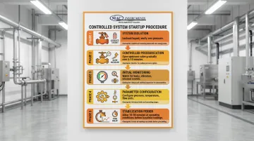
Controlled Startup Procedure:
Perform a slow, controlled startup by gradually opening the upstream isolation valve over 5-10 minutes. Rapid pressurization causes thermal shock and water hammer that can damage meters and piping. ASME B31.1 mandates lagging (insulation) of instrument connections with the steam main to prevent thermal shock at connection points.
Monitor for unusual vibration, noise, or leaks during initial pressurization. Any unusual sounds may indicate water hammer, loose components, or flow disturbances requiring immediate shutdown and investigation.
Parameter Configuration:
Configure meter parameters to match actual operating conditions:
- Pipe size (internal diameter)
- Steam pressure and temperature (for density compensation)
- Flow units (lb/hr, kg/hr, etc.)
- Totalizer settings and scaling
Incorrect density compensation is a common cause of systematic measurement errors. Confirm pressure and temperature inputs match actual measured values at the meter location.
Stabilization Period:
Allow the system to stabilize for 15-30 minutes at normal operating conditions before taking baseline readings or adjusting zero/span settings. Thermal expansion, condensate drainage, and pressure equalization all require time to reach steady state.
For differential pressure systems, confirm impulse lines are fully filled with condensate and all air has vented before performing zero trim. Trapped air creates compressible pockets that cause erratic readings.
Post-Installation Checks and Validation
Leak Detection and Visual Inspection
Conduct a thorough visual inspection for leaks at all flanged connections, packing glands, impulse line connections, and transmitter housings. Use approved leak detection methods—never rely on visual inspection alone for high-pressure steam.
Leak Detection Methods:
- Soap solution test: Apply leak detection solution to all connections while system is pressurized with air (before steam introduction)
- Ultrasonic detection: Use ultrasonic listening devices to detect the high-frequency acoustic signature of escaping steam
- Thermal imaging: Identify temperature anomalies indicating leaks
ASME PCC-2 recommends a sensitive leak test per ASME B31.3 standards. Address all leaks before proceeding—even small leaks worsen over time and compromise safety.
Functional Testing and Performance Verification
Compare flow meter readings against calculated steam consumption from downstream equipment. For example, if a heat exchanger has known heat transfer rates and inlet/outlet temperatures, calculate the required steam flow and compare to meter readings.
Discrepancies exceeding ±10% require investigation. Run the system at steady conditions for 1-4 hours and verify totalizer accumulation matches expected usage. This validates both instantaneous readings and integration accuracy.
Test response time by adjusting control valves and observing meter response. Readings should track changes within seconds for most technologies. Sluggish response indicates damping issues, impulse line blockages, or transmitter configuration problems.
Steam Quality Validation
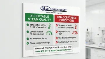
Validate steam quality at the meter location by measuring steam temperature and pressure simultaneously. Calculate the theoretical saturation temperature for the measured pressure using steam tables.
Actual temperature should be within 5-10°F of saturation temperature for dry saturated steam.
If actual temperature significantly exceeds saturation temperature, steam is superheated (acceptable). If actual temperature is below saturation temperature, the measurement is incorrect (instrument error) or steam is wet (unacceptable).
Advanced vortex meters like the Prowirl 200 trigger a "wet steam" alarm if temperature drops to within 2°C (3.6°F) of the saturation curve. If your meter has this capability, verify alarm thresholds are properly configured.
For critical applications, measure actual dryness fraction using calorimetric methods (steam sampling equipment that separates and measures moisture content). Document results as part of your installation baseline.
Installation Documentation
Document the complete installation baseline for future reference and troubleshooting:
- Meter model, serial number, and configuration settings
- Installation date and personnel
- Initial flow readings at multiple operating points (low, normal, high)
- Steam pressure and temperature at meter location
- Photographs showing upstream/downstream piping configuration, straight run distances, and meter orientation
- Torque values used for flange bolts
- Any deviations from standard procedures or manufacturer recommendations
This documentation proves invaluable for warranty claims, troubleshooting future issues, and training new personnel.
Common Installation Problems and Fixes
Inaccurate or Unstable Flow Readings
Problem: Flow readings fluctuate significantly or show consistent offset from expected values.
Likely Causes:
- Wet steam with entrained moisture droplets creates higher differential pressure than dry gas, causing over-reading
- Insufficient straight pipe creates swirl or distorted flow profiles that prevent accurate velocity measurement
- Incorrect density compensation settings cause systematic errors when steam density is calculated from wrong pressure or temperature values
Fix:
- Install or upgrade the steam separator upstream to achieve higher dryness fraction
- Verify separator drain trap is functioning and not allowing condensate to pass through
- Extend straight pipe runs to meet manufacturer minimums (may require piping modifications)
- Recalibrate density compensation using actual measured steam pressure and temperature at the meter location, not design values
- Install a flow straightener to condition the flow profile (verify compatibility with your meter type first)
Premature Meter Failure or Damage
Problem: Meter components eroded, sensing elements damaged, or electronics failed within months of installation.
Likely Causes:
- Water hammer from condensate slugs creates hydraulic shock that shatters sensor bodies and damages electronics
- Flow-Accelerated Corrosion (FAC) when steam velocity exceeds 150 fps or wet steam droplets erode turbine blades and orifice edges
- Electrical damage from improper grounding or lack of surge protection during lightning strikes or electrical surges
Fix:
- Add drain points at all low points in the piping system to improve condensate management
- Upgrade to larger capacity steam traps that handle condensate loads during startup and transient conditions
- Verify separator efficiency (if erosion is occurring, the separator may be undersized or malfunctioning)
- Install surge protection devices on all electrical connections, particularly for outdoor installations in lightning-prone areas
- Review startup procedures to eliminate rapid pressurization—always open valves gradually over 5-10 minutes
Condensate Accumulation in Impulse Lines
Problem: Differential pressure transmitter shows erratic readings, zero flow indication despite steam flowing, or sudden reading jumps.
Likely Causes:
- Impulse lines not sloped correctly allow condensate to pool in low spots, creating air pockets or liquid level differences between legs
- Just 1 inch of liquid height difference creates a pressure error of ~0.036 psi (significant at low flow rates)
- Condensate pots missing or improperly sized cannot maintain equal liquid levels
- Tap positions at 12 o'clock trap gas; positions at 6 o'clock accumulate condensate
Fix:
- Re-route impulse lines with continuous downward slope at minimum 1:12 ratio (8-10% grade) with no low spots where liquid can pool
- Relocate tap positions to 3 o'clock and 9 o'clock positions on horizontal pipes to avoid gas trapping and condensate accumulation
- Install or resize condensate pots per manufacturer specifications, ensuring both pots are at exactly the same vertical height
- Verify condensate pot drain valves are functioning and periodically open them to clear accumulated water and sediment
Pro Tips for Installing Steam Flow Meters Effectively
Time Installation During Planned Shutdowns
Schedule installation during planned maintenance outages to allow proper system cooldown, thorough cleaning, and extended stabilization periods without production pressure. Rushed installations during emergency repairs tempt shortcuts that compromise long-term performance. A well-planned installation saves time and prevents costly rework.
Cold Climate Freeze Protection
For outdoor installations in cold climates, protect all impulse lines, transmitter housings, and meter bodies from freeze damage. Install heat tracing on impulse lines following IEEE 515 standards, selecting wattage to maintain minimum 40°F (4°C) temperature during the coldest ambient conditions.
Use self-regulating heating cables to prevent overheating, and insulate all traced components with weatherproof insulation. Pre-insulated tubing bundles provide consistent thermal performance and simplified installation.
Document Everything
Create comprehensive installation records that include:
- Pre-installation pipe measurements and straight run distances
- Torque values used and configuration settings entered
- Baseline readings at multiple flow points
- Photographs showing piping configuration, meter orientation, and component locations
- Any deviations from standard procedures
This documentation proves invaluable for troubleshooting future issues, warranty claims, and training new personnel.
Establish Manufacturer Relationships
Proper documentation becomes even more valuable when paired with expert technical support.
Contact your meter manufacturer's technical support before installation. Many manufacturers offer pre-installation consultation, startup assistance, and post-installation performance verification services that prevent costly errors.
MAC Instruments provides technical support through experienced application engineers who can help with both standard and custom solutions—contact them at 419-621-2322 or info@macinstruments.com for installation guidance.
Frequently Asked Questions
How should a flow meter be installed?
Install with adequate straight pipe runs (typically 10-25D upstream, 5-10D downstream), ensure dry steam using separators, and position the meter horizontally with correct flow direction. Use eccentric reducers (flat side up) for pipe size changes and always follow manufacturer specifications and ASME B31.1.
What is the minimum distance for a flow meter?
Minimum distance varies by meter type and upstream disturbances: 10-15 pipe diameters after a single elbow, 20-25D after multiple elbows, and 5-10D downstream. Vortex meters require more distance than magnetic meters, so verify your manufacturer's specific requirements.
What is the ISO standard for flow meter?
ISO 5167 covers differential pressure flow meters (orifice, nozzle, Venturi), specifying installation requirements and uncertainty calculations. ASME MFC-3M is the US equivalent for orifice installations. Verify which standards apply to your specific meter type.
Where should a steam flow meter be located in the pipeline?
Position meters after steam separators and strainers, before control valves, and away from bends or tees. Install in horizontal runs with adequate straight pipe, avoiding areas where condensate accumulates or temperature/pressure fluctuations occur.
Do steam flow meters require regular calibration?
Yes, most meters require calibration verification every 1-2 years depending on application criticality and regulatory requirements. Calibration should use NIST-traceable standards. Some meters have built-in diagnostics for drift detection, while others require bench calibration.
What causes inaccurate steam flow meter readings?
The most common causes are wet steam with entrained moisture, insufficient straight pipe creating flow swirl, incorrect density compensation settings, and condensate in sensing lines. Worn internals, improper installation angle, and bypass leaks also affect accuracy.