Introduction
Installation mistakes cost industrial facilities thousands annually in energy waste and measurement errors. Incorrect pipe sizing or improper straight-run piping can cause measurement errors of 5-15%, leading to inaccurate process control and financial losses.
Proper pipe diameter selection and installation are critical for flow meter accuracy, directly affecting measurement reliability, energy efficiency, and operational costs. This guide addresses the key factors that ensure accurate, long-term flow measurement.
What You'll Learn:
- How pipe diameter affects flow meter accuracy and selection
- Required straight-run distances for different meter types
- Installation best practices to minimize measurement errors
- Common sizing mistakes that compromise performance
TL;DR
- Match pipe diameter to flow meter specifications and application flow rates for accurate measurement
- Straight-run requirements vary by technology: magnetic meters need 5 pipe diameters upstream, turbine meters up to 50
- Undersized pipes increase velocity and pressure drop; oversized pipes decrease accuracy
- Bends, valves, and reducers increase required straight-run lengths significantly
- Stay within optimal velocity ranges (1-10 m/s for liquids) to maintain measurement accuracy
Understanding Pipe Diameter and Flow Meter Compatibility
Pipe diameter in flow measurement refers to several related but distinct dimensions. Nominal diameter (DN) is an alphanumeric designation (like DN 50) defined by ISO 6708 as a dimensionless reference indirectly related to physical size.
Inner diameter (ID) is the actual hydraulic diameter used for flow calculations. It's determined by the nominal size and pipe schedule (wall thickness). Schedule affects actual dimensions significantly—a higher schedule number means thicker walls and smaller internal diameter.
The relationship between pipe diameter, flow velocity, and flow meter accuracy is fundamental. Each meter type has optimal velocity ranges where accuracy peaks.
For liquids, industrial applications typically operate at 1-10 m/s (3-33 ft/s). Magnetic flow meters perform best at 0.6-1.8 m/s (2-6 ft/s). Operating outside these ranges reduces accuracy and can cause measurement drift.
These velocity considerations directly affect flow regime. Pipe diameter affects Reynolds number, which determines whether flow is laminar (Re < 2,300), transitional (Re 2,300-4,000), or turbulent (Re > 4,000).
Most industrial flow measurement occurs in the turbulent regime, where velocity profiles are more uniform. Laminar flow creates parabolic velocity profiles that make measurement more difficult.
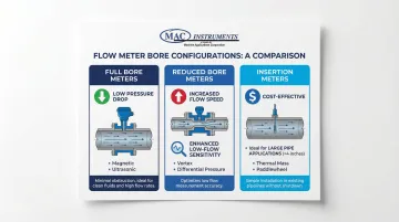
Flow meter bore size doesn't always match pipe diameter. Three common configurations include:
- Full bore meters — Match the pipe ID to minimize pressure drop; common in magnetic and ultrasonic meters
- Reduced bore meters — Use smaller internal diameters to create higher velocity for improved low-flow sensitivity
- Insertion meters — Deploy probes inserted into the pipe for cost-effective measurement in large pipes, though they require careful velocity profile consideration
What to Consider When Selecting Pipe Diameter for Flow Meters
Proper diameter selection balances accuracy, pressure drop, installation cost, and future operational needs. The right choice ensures meters operate within optimal velocity ranges while maintaining acceptable system pressure and energy consumption.
Flow Rate Range and Velocity Requirements
Each flow meter type has optimal velocity ranges where accuracy is highest. Operating outside these ranges reduces measurement reliability and can damage equipment.
Typical velocity ranges:
- General industrial liquids: 0-12 m/s (0-39 ft/s)
- Magnetic flow meters: 0.6-6.1 m/s (2-20 ft/s) preferred
- Abrasive slurries: 0.9-3.1 m/s (3-10 ft/s) to minimize wear
- HVAC/plumbing systems: 0.6-3.0 m/s (2-10 ft/s)
Calculate required pipe diameter from expected flow rates using the continuity equation: Q = V × A, where Q is flow rate, V is velocity, and A is cross-sectional area. For a target velocity of 5 ft/s with 50 GPM flow, a 2-inch pipe provides optimal performance.
Pressure Drop Considerations
Smaller diameters increase pressure drop through friction losses, affecting pump requirements and energy costs. This "energy penalty" becomes a significant lifecycle expense, particularly in systems operating continuously.
Pressure drop becomes critical in gravity-fed systems or applications with limited available pressure. In steam applications, excessive pressure drop can cause condensation and two-phase flow, compromising measurement accuracy.
Balance initial piping costs against long-term energy consumption when selecting diameter.
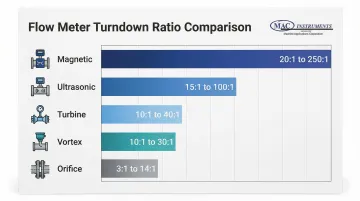
Turndown Ratio and Flow Variability
Turndown ratio—the ratio of maximum to minimum measurable flow within accuracy specifications—varies significantly by technology:
| Meter Type | Turndown Ratio | Application Notes |
|---|---|---|
| Magnetic | 20:1 to 250:1 | Excellent low-flow sensitivity |
| Ultrasonic | 15:1 to 100:1 | Some models reach 250:1 |
| Turbine | 10:1 to 40:1 | Limited by mechanical friction |
| Vortex | 10:1 to 30:1 | Requires minimum Reynolds number |
| Orifice | 3:1 to 14:1 | Modern transmitters improve range |
Oversizing pipe diameter for peak flows may cause poor accuracy at normal operating flows. If your process typically runs at 30% of peak capacity, select a diameter that maintains velocity within the optimal range during normal operation, not just peak conditions.
Fluid Properties and Application Type
Viscosity, temperature, and fluid type significantly influence diameter selection. High-viscosity fluids affect Reynolds number and velocity profile development.
Coriolis and positive displacement meters handle viscous fluids better than turbine meters, which suffer from slip and linearity loss.
High-temperature applications like steam require consideration of thermal expansion. For extreme conditions, MAC Instruments manufactures steam flow meters that handle temperatures up to 1200°F (650°C), with optional capability to 2400°F (1300°C)—requiring pipe materials and expansion compensation appropriate for these conditions.
Gas density changes with pressure, significantly impacting mass flow calculations in volumetric meters like vortex and turbine designs. Temperature and pressure compensation become essential for accurate measurement.
Installation Space and Cost Constraints
Beyond fluid considerations, physical installation requirements affect diameter selection. Larger diameters require more straight-run length, potentially creating space constraints in existing facilities.
A turbine meter in 6-inch pipe may require 50D (25 feet) upstream clearance with certain disturbances, while a magnetic meter in the same size needs only 5D (2.5 feet).
Balance upfront costs—larger meters, more piping, additional supports—against long-term operational costs including energy consumption and maintenance. In retrofit applications, space limitations may dictate meter technology selection as much as diameter choice.
Future Expansion and Process Changes
Consider potential flow increases or process modifications when selecting diameter. Installing a larger pipe now may handle future capacity without requiring complete system replacement.
However, oversizing creates a trade-off. A pipe sized for future 100 GPM capacity will operate at low velocity when current flow is only 40 GPM, potentially reducing accuracy below acceptable limits.
Consider installing reducers that can be removed during future expansion, or select meter technologies with high turndown ratios that maintain accuracy across wide flow ranges.
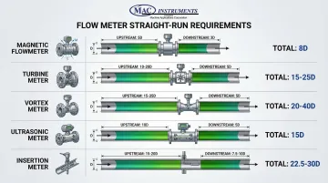
Straight-Run Piping Requirements by Flow Meter Type
Straight-run requirements are expressed as multiples of pipe diameter (such as "10D") to ensure stable flow profiles for accurate measurement.
Upstream straight-run reduces swirl and velocity profile distortion. Downstream straight-run prevents backpressure effects and ensures proper flow recovery.
Insertion Flow Meters
Insertion meters sample flow at specific points, which makes them highly sensitive to velocity profile distortions.
Requirements:
- Small pipes (< 6 inches): 20D upstream, 10D downstream
- Large pipes (≥ 6 inches): 15D upstream, 7.5D downstream
Smaller pipes require longer straight runs because disturbances have proportionally greater impact. A single elbow disrupts flow more severely in a 2-inch pipe than in a 12-inch pipe.
Turbine Flow Meters
The rotating components in turbine meters respond directly to swirl and asymmetric flow patterns, requiring substantial straight-run distances.
Requirements:
- Standard installation: 10-20D upstream, 5D downstream
- After partially open valves: 25D upstream
- Multiple disturbances: Up to 50D upstream
- With flow straighteners: Reduced to 5D upstream
Turbine meters can experience significant errors when installed with inadequate straight run.
The rotating element responds to swirl-induced tangential flow, causing measurement errors or premature bearing wear.
Magnetic Flow Meters
Magnetic flow meters measure voltage generated as conductive fluid moves through a magnetic field, making them less sensitive to flow profile than mechanical meters.
Requirements:
- Standard: 5D upstream, 3D downstream (from electrode plane)
- Vertical installation with upward flow preferred
- Zero-run capable in some applications (with 0.5% accuracy shift)
Even robust magnetic meters benefit from adequate straight-run. Inadequate installation can cause measurement drift of 1.5% or more with severe swirl or uneven flow profiles.
Vortex Flow Meters
Vortex meters detect pressure oscillations created by vortices shedding from a bluff body in the flow stream.
Requirements:
- Standard: 15-35D upstream, 5D downstream
- Control valve (gas): 30D upstream
- Control valve (liquid): 5D downstream preferred
- Pipe must be completely full
Vortex meters respond to swirl and velocity profile distortion. Reducing upstream length from 35D to 10D can cause K-factor shifts up to 0.5%, directly affecting measurement accuracy.
Ultrasonic Flow Meters
Ultrasonic meters measure transit time differences of sound waves traveling with and against flow.
Requirements:
- Multi-path meters: 5D minimum upstream
- Single-path meters: 10-20D upstream
- General guideline: 10D upstream, 5D downstream
- Clamp-on installations: Follow manufacturer specifications
Multi-path meters with multiple measurement chords are less sensitive to profile distortion than single-path designs. However, inadequate straight-run increases error by approximately 1% even in advanced designs.
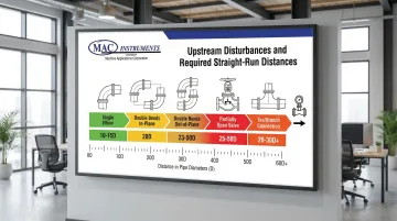
Installation Conditions That Affect Straight-Run Requirements
Elbows, valves, tees, reducers, and other piping elements create flow disturbances requiring additional straight-run compensation.
The severity of disturbance depends on the element type and configuration.
Single Elbows and Bends
90-degree elbows typically require 10-15D upstream depending on meter type.
Long-radius bends create less turbulence than short-radius bends, reducing required straight-run by 20-30%.
Insertion meters need 8D upstream clearance for a single in-plane elbow. The elbow creates uneven velocity profiles that take several pipe diameters to return to normal flow.
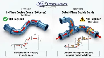
Double Bends and Out-of-Plane Configurations
Multiple elbows compound the flow disturbance. Bends in different planes create swirl, requiring 20-50D upstream depending on configuration.
Out-of-plane bends are particularly problematic because they induce rotational flow components.
Bend Configuration Requirements:
| Configuration | Meter Type | Upstream Distance Required |
|---|---|---|
| In-plane double bends (S-curves) | Insertion | 11D |
| Out-of-plane double bends | Insertion | 23D |
| Out-of-plane double bends | Orifice | Up to 60D |
In-plane configurations cause less disturbance because flow distortion remains in a single plane, making recovery faster.
Valves and Flow Control Devices
Valve position dramatically affects flow disturbance. Partially open valves create severe turbulence requiring 25-50D upstream.
Fully open gate valves require less—typically matching single elbow requirements.
Best practices:
- Install control valves downstream of flow meters with 5D+ spacing
- Use full-port ball valves for isolation (minimal disturbance when fully open)
- Avoid butterfly valves immediately upstream (require 20-30D clearance)
Application-specific valve placement:
- Vortex meters (gas): Control valves can be placed 30D upstream
- Vortex meters (liquid): Downstream placement (5D minimum) prevents cavitation
Reducers and Expanders
Diameter changes affect flow patterns based on transition geometry:
- Reducers: 5-10D upstream
- Expanders: 10-20D upstream (depending on size change)
Gradual tapers (7-15 degree included angle) create less disturbance than abrupt diameter changes.
Abrupt expansions create recirculation zones and highly turbulent flow. This requires extended recovery distance.
Gradual reducers maintain more uniform velocity profiles, reducing straight-run requirements by 30-40%.
Tees, Headers, and Branch Connections
Branch connections represent some of the most challenging installation conditions. Tees create highly uneven flow requiring 20-30D+ upstream.
Flow from branch connections introduces lateral velocity components that persist for significant distances.
Considerations for branch installations:
- Evaluate flow from each branch and potential pulsation effects
- Account for flow distribution between branches in headers (creates complex velocity profiles)
- Consider flow conditioners or relocate meters to positions with better flow conditions
How MAC Instruments Can Help
MAC Instruments brings over 30 years of expertise in industrial flow measurement, particularly for high-temperature applications like steam where proper pipe diameter and installation are critical.
With NIST-traceable measurement capabilities, MAC helps industries achieve accurate flow measurement in demanding environments.
MAC's Steam Flow Meters and Installation Guidance
MAC's steam flow meters are designed specifically for high-temperature steam applications with tailored piping requirements. The meters use proprietary venturi flow nozzle technology to provide true mass flow measurement even with changing line pressure conditions.
Key specifications include:
- Pipe sizes from 1 to 3 inches
- Flow capacities from 125 to 5,000 LB/HR
- 300 series stainless steel construction
- Rated pressures up to 150 PSIG
- Ambient temperatures from 32°F to 180°F
MAC's engineering team provides installation specifications and pipe diameter consultation for steam applications:
- Atmospheric blanchers
- Steam injection to process ovens
- Humidification systems
- Boiler efficiency monitoring
The team ensures proper sizing based on your specific steam flow requirements, operating pressures, and installation constraints.
Proper installation ensures compliance with emission monitoring requirements and improved process efficiency.
The meters deliver ±5% full-scale accuracy with a mechanical design featuring no internal moving parts—providing reliable performance for system evaluation, boiler efficiency assessment, and process optimization across power generation, food processing, chemical manufacturing, and pulp and paper industries.
Conclusion
Accurate flow measurement depends on both proper pipe diameter selection and correct installation with adequate straight-run piping. Errors from improper sizing or installation can reach 5-20%, directly impacting process control, custody transfer accuracy, and energy efficiency.
Match pipe diameter to your specific application requirements rather than following generic sizing rules:
- Flow rate, pressure, and accuracy needs for your process
- Fluid properties and velocity ranges
- Turndown ratios and future expansion plans
- Pressure drop considerations
- Manufacturer-specific straight-run requirements
- Installation conditions including bends, valves, and fittings
For steam flow applications, manufacturers like MAC Instruments provide detailed specifications for their steam flow meters and transmitters to ensure proper installation. Always account for site-specific conditions during setup. Periodic verification through calibration checks ensures continued accuracy throughout the meter's service life.
Frequently Asked Questions
How many pipe diameters for a flow meter?
Requirements vary by meter type. Magnetic flow meters typically need 5D upstream and 3D downstream, turbine meters require 10-20D upstream and 5-10D downstream, while vortex meters need 15-35D upstream and 5D downstream. Complex installations with bends or valves significantly increase these requirements.
What size pipe do I need for 50 gpm?
For 50 GPM at optimal velocity (3-8 ft/s for water), a 2-inch pipe produces approximately 5 ft/s, which is ideal for most applications. A 1.5-inch pipe produces approximately 9 ft/s, which may be acceptable depending on pressure drop tolerance and system constraints.
Does smaller diameter pipe increase flow rate?
No—smaller diameter increases flow velocity, not flow rate. Flow rate (GPM or m³/h) is determined by your system, not pipe size. Reducing diameter increases velocity proportionally, which affects pressure drop and pump performance but doesn't change volumetric flow.
What size pipe comes off a water meter?
Pipe size typically matches the meter outlet size based on expected flow rates. Residential meters use 3/4 inch to 1 inch, while commercial and industrial installations range from 2 inches to 12 inches or larger.