Introduction
Flow measurement errors of 20-50% aren't just numbers on a screen. They translate to billing disputes, failed compliance audits, and process inefficiencies that cost thousands per incident.
Pressure-temperature (P/T) compensation transforms volumetric ultrasonic flow measurements into accurate mass flow data. Without it, your measurements will drift significantly as operating conditions change.
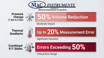
Gases are compressible—pressure and temperature variations dramatically change their density. Consider these impacts:
- Pressure change from 1 bar to 2 bar: 50% volume reduction
- Thermal gradients alone: up to 20% measurement error
- Combined P/T shifts: errors exceeding 50% in extreme conditions
This article explains how P/T compensation works, when it's required, and how to implement it correctly for reliable ultrasonic flow measurement.
TL;DR
- P/T compensation corrects for density changes, converting volumetric flow to accurate mass flow
- Real-time P/T inputs enable calculation of standard volume (Nm³/h) or mass flow rates
- Uncompensated meters measure actual volume only—acceptable only when pressure and temperature remain constant
- Accurate compensation requires proper sensor placement, gas composition data, and correct reference conditions
- For custody transfer, billing, and regulatory applications, P/T compensation is mandatory
What Pressure-Temperature Compensation Represents in Ultrasonic Flow Meters
P/T compensation is the mathematical correction process that accounts for gas and steam density changes due to pressure and temperature variations in volumetric flow measurements. Ultrasonic meters measure velocity and calculate volumetric flow, but gases are compressible—their density changes dramatically with pressure and temperature shifts.
Compensation converts "actual" conditions (the operating state) to "standard" or "normal" conditions (typically 1 atm at 0°C or 15°C), enabling fair comparisons and accurate mass flow calculation.
This distinction is fundamental:
- Volumetric flow (actual): Volume at operating conditions (m³/h, ACFM)
- Standard volumetric flow: Volume corrected to reference conditions (Nm³/h, SCFM)
- Mass flow: Actual mass passing through the meter (kg/h, lb/h)
Why Compensation Is Critical
Without compensation, a 10% pressure increase causes approximately a 10% density increase. The actual volume flow appears constant, but mass flow has actually increased by 10%.
The meter reports the same volumetric rate, but you're moving significantly more mass through the system.
Failing to account for thermal gradients in ultrasonic measurement can lead to errors reaching 20%. In high-pressure natural gas applications where pressure swings of 30% are common, uncompensated measurements can deviate by the same 30% in mass terms.
Consequences of uncompensated measurement:
- Incorrect billing and custody transfer disputes
- Process inefficiency and poor control
- Regulatory non-compliance and potential fines
- Energy waste from inaccurate flow data
- Inability to detect leaks or system losses
Financial Impact of Measurement Errors
For a 12-inch meter flowing 200 MMSCFD (million standard cubic feet per day), a mere 0.2% measurement error translates to over $300,000 in annual financial variance at $2/MSCF gas prices.
How Pressure-Temperature Compensation Works in Ultrasonic Flow Meters
A flow computer or transmitter performs compensation by receiving three inputs: volumetric flow from the ultrasonic meter, real-time pressure measurement, and real-time temperature measurement. These inputs feed into thermodynamic equations that calculate corrected flow.
The Gas Laws: Foundation of Compensation
The ideal gas law (PV=nRT) and the combined gas law form the foundation of P/T compensation. The state equation used for compensation is:
(P₁ × V₁) / T₁ = (P₂ × V₂) / T₂
Variable definitions:
- Subscript 1 represents actual (operating) conditions
- Subscript 2 represents standard (reference) conditions
- P = absolute pressure
- V = volume
- T = absolute temperature
Simple calculation example:
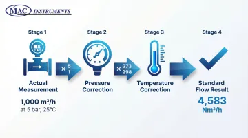
An ultrasonic meter measures 1,000 m³/h at operating conditions of 5 bar absolute and 25°C (298K). Convert to standard conditions of 1 bar absolute and 0°C (273K):
Q_standard = Q_actual × (P_actual / P_standard) × (T_standard / T_actual)
Q_standard = 1,000 × (5 / 1) × (273 / 298) = 4,583 Nm³/h
The actual volumetric flow of 1,000 m³/h represents 4,583 Nm³/h at standard conditions—a difference of 358%.
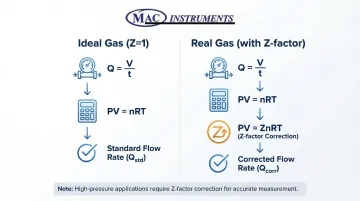
Compressibility Factor (Z-Factor) for Real Gases
Real gases don't behave ideally, especially at high pressure or with hydrocarbon mixtures. The Z-factor (compressibility factor) corrects for this non-ideal behavior. It varies with pressure, temperature, and gas composition.
The complete compensation equation incorporating Z-factor is:
Q_standard = Q_actual × (P_actual / P_standard) × (T_standard / T_actual) × (Z_standard / Z_actual)
For natural gas custody transfer (commercial measurement requiring high accuracy), calculation methods include:
- AGA 8 Detail Characterization: Industry standard requiring full composition (up to 21 components), accurate to within 0.1%
- GERG-2008 (ISO 20765-2): Wide-range equation of state for natural gas and other mixtures
- NX-19: Older simplified method with potential errors up to 2% versus AGA 8
The Z-factor simplifies to 1 under specific conditions. This assumption works at low pressures (near atmospheric), for pure gases like hydrogen or helium, or when high accuracy isn't critical.
For custody transfer and high-pressure applications, assuming Z=1 creates unacceptable errors.
Mass Flow Calculation
Mass flow calculation requires standard volumetric flow multiplied by standard density. This requires knowledge of gas composition or molecular weight:
Mass flow = Q_standard × ρ_standard
Some ultrasonic transmitters calculate mass flow directly if gas properties are configured in the device. The transmitter continuously updates the calculation based on real-time P/T inputs and the programmed gas composition.
Key Properties and Characteristics of Compensated Ultrasonic Systems
Compensated systems have distinct performance characteristics that differ fundamentally from uncompensated meters.
Measurement Range and Turndown
Compensated systems maintain accuracy across wide pressure and temperature ranges. Modern gas ultrasonic meters achieve rangeabilities exceeding 100:1, meaning they accurately measure flows from 1% to 100% of maximum capacity.
Proper compensation preserves this excellent turndown—correction algorithms work equally well at low and high flows.
Flow-calibrated ultrasonic meters can achieve accuracy as tight as ±0.1% of reading over the entire calibration range, far exceeding differential pressure meters that degrade significantly at low flows.
Response Time and Dynamic Performance
While accuracy across flow ranges is critical, response speed also affects compensated system performance. Compensation adds minimal lag if pressure and temperature sensors respond quickly. Modern transmitters update compensation calculations multiple times per second, making the delay imperceptible in most applications.
Sensor response time becomes critical during rapid load changes—power boiler cycling, batch processes, or systems responding to renewable energy fluctuations. A slow temperature sensor (5-10 second response) can introduce temporary measurement errors during transients, even though steady-state accuracy is excellent.
Accuracy Statement Complexity
Beyond dynamic response, steady-state accuracy depends on how well multiple measurement uncertainties combine.
Compensated system accuracy combines multiple uncertainties:
- Ultrasonic meter accuracy: ±0.5-1% of reading
- Pressure transmitter accuracy: ±0.1-0.25% of span
- Temperature sensor accuracy: ±0.5°C
- Z-factor uncertainty: ±0.1-0.5% depending on method and composition knowledge
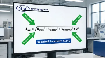
Combined uncertainty uses the root-sum-square (RSS) method:
U_total = √(U_meter² + U_pressure² + U_temperature² + U_z²)
For a system with ±0.5% meter, ±0.15% pressure, ±0.3% temperature (as % of flow), and ±0.2% Z-factor:
U_total = √(0.5² + 0.15² + 0.3² + 0.2²) = ±0.64%
This calculation shows overall system accuracy typically achieves ±1-2% of mass flow rate—still superior to differential pressure flowmeters, especially at low flows where DP devices can exceed ±5% error.
Factors That Influence Compensation Accuracy in Real-World Operation
Theoretical compensation is straightforward, but field conditions introduce variables that significantly affect accuracy.
Sensor Location and Installation Quality:
Pressure taps must be located close to the flow measurement point to minimize gauge line errors. AGA Report No. 9 requires pressure taps on the meter body itself to ensure the reading corresponds exactly to the measurement volume.
Long gauge lines introduce hydrostatic head errors and temperature gradients that distort the pressure reading.
Temperature sensors require proper immersion depth to avoid stem conduction errors. Key installation requirements include:
- Thermowell placement 2D to 5D downstream of the meter (where D = pipe diameter)
- Immersion length at least 10 times the thermowell diameter
- Minimum 3 inches plus the sensitive length
Dead legs where condensate can form create significant errors. Gauge lines should be self-draining and heat-traced in steam applications to prevent liquid accumulation.
How Gas Composition Affects Accuracy:
Beyond installation quality, operational variables introduce significant measurement challenges. Changing gas composition affects molecular weight and Z-factor in ways that fixed assumptions cannot accommodate.
For custody transfer natural gas, composition variability creates these accuracy issues:
- Variations in ethane, CO2, or nitrogen content alter speed of sound and density beyond acceptable uncertainty
- Speed of sound prediction inconsistencies between equations of state can reach 0.2% for ethane-rich mixtures
- Fixed composition assumptions introduce systematic errors in custody transfer applications
A gas chromatograph (GC) input becomes necessary for continuous Z-factor updates based on real-time composition data.
Reference Condition Selection:
Standard conditions vary by region and industry, and selecting the wrong reference creates systematic errors. Common standards include:
- IUPAC (Scientific): 0°C and 1 bar (100 kPa)
- U.S. Oil & Gas: 60°F (15.56°C) and 14.73 psia
- International Gas: 15°C and 1 atm (101.325 kPa)
- NIST: 20°C and 1 atm
Reference conditions must match contractual or regulatory requirements exactly. A contract specifying 15°C while the flow computer uses 0°C introduces a 5.5% systematic error in standard volume.
How P/T Compensation Is Specified, Measured, and Validated
Compensation is both a design specification and an operational verification requirement.
Specification and Configuration
Key parameters that must be specified include:
- Reference pressure and temperature (e.g., 1 atm, 15°C)
- Gas composition or molecular weight
- Z-factor calculation method (AGA 8, GERG-2008, etc.)
- Units of measure (Nm³/h, SCFM, kg/h, etc.)
- Sensor accuracy classes and ranges
Engineers program these parameters into the flow computer or transmitter during commissioning. The configuration must align with industry standards that govern compensation calculations:
- ISO 17089-1: Ultrasonic meters for custody transfer and allocation
- AGA Report No. 9: Multipath ultrasonic meters
- AGA Report No. 8: Thermodynamic properties and Z-factor
- ISO 5167: Differential pressure devices (provides general P/T compensation framework)
Sensor Selection and Installation
Pressure Transmitters:
- Custody transfer applications: ±0.075% to ±0.1% reference accuracy
- High-performance models: ±0.065% of calibrated span (e.g., Rosemount 2088)
- Must include NIST-traceable calibration certificates
Temperature Sensors:
- Accuracy requirement: ±0.5°C for custody transfer
- RTD (resistance temperature detector) sensors preferred over thermocouples
- Superior accuracy and long-term stability
Installation Best Practices:
Close-coupled manifolds mount sensors directly on the meter body or within a few pipe diameters. This reduces leak points and gauge line errors.
The configuration minimizes hydrostatic head errors and condensate accumulation. NIST-traceable calibration ensures sensors meet specifications—manufacturers like MAC Instruments maintain this capability as a standard of quality.

Validation and Verification Methods
Speed of Sound Cross-Check:
Ultrasonic meters measure speed of sound directly as part of their operating principle. This measured value can be compared to a theoretical speed of sound calculated from pressure, temperature, and composition using AGA Report No. 10. Differences indicate sensor drift, composition errors, or meter problems.
Independent Verification:
Compare indicated mass flow to calculated mass flow using independent, calibrated pressure and temperature readings. Perform this verification during commissioning. Repeat annually or semi-annually.
Periodic Calibration:
EPA Part 75 recommends calibrating pressure and temperature instruments upon installation and repeating based on manufacturer instructions. Use NIST-traceable references with ±0.5% uncertainty.
Ultrasonic meter bodies remain stable for years. However, P/T sensors require more frequent calibration—typically annually.
Diagnostic Capabilities:
Modern ultrasonic transmitters monitor compensation quality through built-in diagnostics. They track sensor status, detect out-of-range conditions, and alarm when P/T inputs fall outside expected bounds.
Compensated vs. Uncompensated Ultrasonic Flow Meters
Uncompensated meters report only actual volumetric flow at operating conditions without correction. They measure the volume passing through the meter at whatever pressure and temperature exists at that moment.
Uncompensated measurement is acceptable when:
- Pressure and temperature remain essentially constant
- The application requires only relative measurement for control purposes
- Measuring liquid flow where density changes are minimal
- Cost constraints prohibit compensation and accuracy requirements are loose
However, many industrial applications demand precision that uncompensated meters cannot provide.
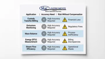
When Compensation Is Mandatory
Compensation becomes critical in applications where accuracy directly impacts operations, compliance, or costs:
Custody transfer and billing: Standards like ISO 17089-1 and AGA 9 mandate P/T compensation when flow measurements determine financial transactions, with typical system uncertainties of 0.7-1.0%
Regulatory emissions monitoring: EPA Part 75 requires CEMS to convert volumetric flow to standard conditions using F_STP = F_Actual × (T_Std / T_Stack) × (P_Stack / P_Std). Failure to report at standard conditions constitutes a violation subject to fines
Mass balance calculations: Plant-wide energy accounting requires mass flow data, since only mass—not volume—is conserved across pressure and temperature changes
Energy (BTU) measurement: Energy flow calculations require mass flow multiplied by specific enthalpy. Volumetric flow without density correction produces meaningless results
Steam flow for efficiency calculations: Boiler efficiency, turbine performance, and steam system optimization depend on accurate mass flow. Steam density varies dramatically with pressure and temperature, making compensation essential
Implications of Operating Without Proper P/T Compensation
Skipping compensation or implementing it incorrectly creates systematic errors with serious consequences.
Measurement Errors and Magnitude
A 30% pressure swing produces a 30% mass flow error if uncompensated. Consider a natural gas pipeline operating between 800 and 1,200 psig—a 50% pressure variation. Uncompensated volumetric flow shows the same reading while actual mass flow varies by 50%.
Temperature swings add to these pressure-driven errors. A 50°C temperature increase at constant pressure reduces gas density by approximately 15%, creating an additional 15% error in mass terms.
Financial and Operational Impact
Uncompensated flow creates measurable financial damage:
- Billing disputes: Custody transfer errors trigger disputes between buyers and sellers, with potential losses of hundreds of thousands of dollars annually on large pipelines
- Energy waste: Incorrect flow data prevents optimization of combustion and steam systems, increasing energy consumption by 5-15%
- Process inefficiency: Poor control from inaccurate data leads to quality issues, off-spec product, and higher raw material consumption
- Leak detection failure: Mass balance calculations require compensated flow at all measurement points—without it, leaks go undetected
Compliance and Safety Risks
Regulatory non-compliance: Emissions monitoring regulations require standard volumetric flow. Reporting uncompensated actual flow violates EPA Part 75 and similar regulations, and facilities face enforcement actions.
Safety implications: Combustion control requires accurate fuel mass flow to maintain proper air-fuel ratios. Uncompensated volume readings during pressure transients can create dangerous fuel-rich or fuel-lean conditions, risking equipment damage, efficiency loss, or safety incidents.
Common Misinterpretations and Mistakes with P/T Compensation
Operators frequently encounter these compensation pitfalls:
Assuming compensation is "built-in" Many operators believe all modern ultrasonic meters include automatic P/T compensation. They don't—compensation must be explicitly configured, and pressure/temperature sensors must be provided and properly installed.
Wrong reference conditions Specifying 0°C when the contract requires 15°C, or using 14.7 psia when 14.73 psia is required, introduces systematic errors.
Always verify reference conditions match contractual and regulatory requirements exactly.
Neglecting Z-factor For high-pressure or hydrocarbon applications, assuming Z=1 leads to 2-5% errors.
Natural gas at 1,000 psig typically has Z ≈ 0.85-0.90, meaning the ideal gas assumption creates a 10-15% error.
Poor sensor installation Installing pressure taps far from the flow measurement point or temperature sensors in dead legs introduces errors that eliminate the ultrasonic meter's inherent accuracy.
Outdated gas composition data When process gas composition changes (switching gas sources, seasonal variations, or process modifications), the flow computer's composition data must be updated.
Outdated composition data produces incorrect Z-factors and densities.
Applying liquid methods to gases Liquid compensation (for thermal expansion) uses completely different equations than gas compensation. Mixing the two creates massive errors.
Conclusion
P/T compensation transforms ultrasonic volumetric flow measurement into accurate mass flow data by correcting for density changes caused by pressure and temperature variations. For compressible fluids like natural gas and steam, this correction is the difference between 20-50% measurement error and sub-1% system accuracy.
Proper compensation requires correct sensor installation, appropriate gas property data (including Z-factor calculations), and regular verification. This isn't a "set and forget" function: sensors drift, compositions change, and systems need periodic validation.
Beyond operational requirements, engineering judgment in selecting reference conditions, Z-factor methods, and sensor specifications matters as much as the published formulas. A technically correct calculation using the wrong reference conditions or outdated composition data produces systematically wrong results.
For custody transfer, regulatory compliance, and any application where accurate mass flow matters, P/T compensation isn't optional: it's the foundation of measurement integrity.
Frequently Asked Questions
What is pressure and temperature compensation in ultrasonic flow meters?
P/T compensation corrects volumetric flow measurements for density changes caused by varying pressure and temperature. It converts actual volume at operating conditions to standard volume or mass flow.
What is the difference between compensated and uncompensated ultrasonic flow meters?
Compensated meters include pressure and temperature inputs to calculate corrected flow (standard volume or mass). Uncompensated meters report only actual volumetric flow at operating conditions.
When is P/T compensation required for ultrasonic flow measurement?
Compensation is required for custody transfer, billing, regulatory compliance (EPA emissions monitoring), mass balance calculations, and applications where pressure/temperature vary significantly or accurate mass flow is needed.
Can I add compensation to an existing uncompensated ultrasonic meter?
If the transmitter has compensation capability, you can add pressure and temperature sensors and configure accordingly. Otherwise, an external flow computer calculates compensated flow from the volumetric signal and P/T inputs.
How accurate is P/T compensation in ultrasonic flow meters?
Combined system uncertainty depends on all sensor accuracies but typically achieves ±1-2% of mass flow rate. This is superior to differential pressure systems, especially at low flows where DP devices can exceed ±5% error.
What happens if my pressure or temperature sensor fails during operation?
Most transmitters alarm and either hold last-known compensation values, switch to uncompensated mode, or stop outputting flow. Critical applications should include redundant sensors or automatic failover strategies.