Introduction
Accurate moisture readings in boiler exhaust are essential for combustion efficiency, emissions compliance, and process control. Many facilities struggle with maintaining reliable moisture data — challenges range from sensor contamination to installation errors. Research shows that moisture losses typically account for 6-10% of total boiler efficiency losses, making precise measurement directly tied to fuel consumption and operating costs.
When readings drift off, the consequences compound quickly. Under EPA 40 CFR Part 75, facilities with failed moisture monitoring systems must apply "missing data substitution" procedures — rules that artificially inflate reported emissions and increase regulatory exposure.
Poor measurement also masks physical risks. Acid dew point corrosion, a direct consequence of undetected moisture fluctuations, has caused documented failures in flue gas sensors and boiler tubes. A case study of an 89 MW generator found that a 0.29% efficiency improvement through better combustion control alone yielded approximately $217,000 in annual savings.
Key Takeaways
- Sensor contamination from ash, sulfur, and combustion byproducts creates measurement drift
- Aging sensors and skipped calibrations erode accuracy over time
- Wrong probe placement and inadequate probe heating produce distorted readings
- These inaccuracies waste fuel, trigger regulatory violations, and damage equipment
- Quarterly calibration, correct sensor placement, and instruments with built-in calibration systems prevent these failures
Common Causes of Inaccurate Boiler Exhaust Moisture Readings
Boiler exhaust moisture readings measure the water vapor content in combustion gases, typically expressed as percent moisture by volume. Accuracy matters because these measurements drive efficiency calculations, emissions reporting, and process control decisions. Inaccuracies typically arise from four primary sources: sensor contamination, calibration drift, installation problems, and temperature-related errors.
Sensor Contamination and Fouling
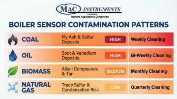
Particulates, sulfur compounds, and combustion byproducts coat moisture sensors over time, creating an insulating layer that distorts measurements. The contamination mechanism varies significantly by fuel type:
Fuel-Specific Contamination Patterns:
- Coal-fired boilers: High fly ash content deposits particulate matter on sensor surfaces, while sulfur compounds form acidic condensates that etch and corrode sensing elements
- Oil-fired systems: Sticky soot and vanadium deposits coat sensors, with heavy oil combustion producing high sulfur levels that promote acid formation
- Biomass boilers: Alkali compounds (potassium, chloride) create sticky deposits, while tar formation in non-woody biomass combustion poses significant fouling risks
- Natural gas systems: While cleaner, trace sulfur and high water vapor content (120-130°F dew point) still create condensation and contamination risks
Contamination creates a progressive insulating barrier between the sensing element and the gas stream. In coal-fired applications, significant drift can occur within 2-4 weeks without proper filtration. Biomass operations often see tar accumulation that requires weekly cleaning to maintain accuracy.
The 10-micron filters commonly used in industrial analyzers provide protection but require regular inspection and replacement based on fuel type — monthly for heavy fuels, quarterly for clean natural gas.
Calibration Drift and Sensor Aging
Sensors lose accuracy over time due to thermal cycling, exposure to corrosive gases, and material degradation. The drift rate depends heavily on sensor technology:
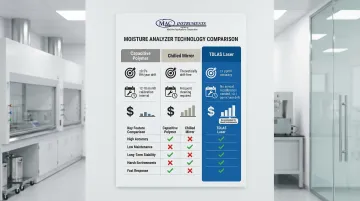
Sensor Technology Drift Characteristics:
| Technology | Typical Drift Rate | Stability Notes |
|---|---|---|
| Capacitive Polymer | ±0.5% RH/year (clean environments) | Chemical contamination accelerates drift; industrial units show <2% RH drift over 12 months |
| Chilled Mirror | Theoretically drift-free | Mirror contamination causes false dew/frost readings; requires frequent cleaning in dirty stacks |
| TDLAS (Laser) | <0.1 ppmV/year | Highest stability; no annual recalibration required in many applications |
Drift accelerates dramatically in harsh conditions. High-temperature applications above 1000°F, acidic exhaust environments with pH below 5, and frequent thermal shocks from load cycling can double or triple normal drift rates. Traditional capacitive sensors may require recalibration every 3-6 months in coal-fired applications versus 12-18 months in natural gas systems.
Research on industrial installations shows that sensors in coal-fired power plants experience drift rates 2-3 times higher than those in natural gas facilities. Left unchecked, this drift compounds into measurement errors exceeding 5% within a year — invalidating emissions data and triggering regulatory substitute value requirements. Sensor placement and installation quality determine how quickly those errors accumulate.
Improper Sensor Installation and Placement
Incorrect probe positioning creates localized measurement errors that don't represent actual exhaust conditions. Common installation mistakes include:
Critical Installation Errors:
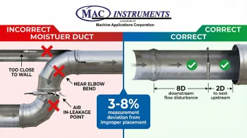
- Inadequate insertion depth: Probes installed too close to duct walls measure cooler, stratified gas rather than representative bulk flow
- Condensation zones: Installation at points where moisture has already condensed (typically in cooler sections downstream) produces falsely low readings
- Turbulent flow areas: Placement near elbows, dampers, or flow obstructions creates measurement instability
- Air in-leakage proximity: Sensors near duct penetrations or access doors measure diluted gas, skewing readings 2-5% lower than actual exhaust moisture
EPA Method 4 mandates sampling at multiple traverse points (typically 8-12) to account for moisture stratification in large ducts. Single-point measurements can deviate from true average moisture content by 3-8% depending on duct size and flow conditions. Proper installation requires centerline placement or multi-point averaging in ducts larger than 24 inches in diameter.
Temperature stratification compounds installation problems. In large stacks operating at low loads, temperature differences between centerline and wall can exceed 100°F, creating corresponding moisture gradients. Sensors positioned in these stratified zones report values that don't represent bulk exhaust conditions.
Temperature-Related Measurement Errors
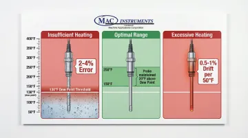
Water vapor condenses when gas temperature drops below its dew point — typically 120-130°F for natural gas combustion and 140-160°F for coal and oil. When probe temperatures aren't managed to stay above that threshold, condensation occurs before the sensor can measure it. Temperature-related errors take three distinct forms:
- Insufficient probe heating: Probe surfaces must stay at least 20°F above the water dew point. In natural gas applications with 130°F dew points, heating below 150°F causes measurement errors of 2-4% moisture content — the most common temperature-related failure
- Excessive heating: Probes heated above 250°F risk damaging polymer-based sensors or creating thermal gradients that skew capacitive measurements. Some sensor technologies show 0.5-1% measurement drift for every 50°F of excess heating above recommended levels
- Ambient temperature fluctuations: Day/night swings of 40-50°F create thermal cycling that stresses sensor electronics and causes baseline drift. Winter conditions below 32°F require heated enclosures to prevent condensation in junction boxes
What Happens If Inaccurate Moisture Readings Are Ignored
Ignoring inaccurate moisture readings triggers cascading operational problems. Efficiency calculations become unreliable, masking fuel waste that compounds into hundreds of thousands of dollars annually.
Regulatory reporting is equally affected. When readings fail quality assurance requirements, facilities get pushed into missing data substitution protocols that artificially inflate reported emissions and can trigger allowance surcharges.
Beyond compliance, equipment damage accelerates when moisture data doesn't reflect actual conditions. Acid dew point corrosion sets in when flue gas temperatures drop below the condensation point of sulfuric or hydrochloric acid vapors — a condition that goes undetected without reliable readings. Sensor failure within 6-12 months and boiler tube corrosion in convection sections are two documented outcomes of running equipment on bad moisture data.
Warning Signs You're About to Experience Measurement Issues
Watch for these indicators:
- Moisture readings shift >2% during stable operating conditions with no corresponding fuel or load changes
- Measured moisture diverges from values expected based on fuel composition and stoichiometric combustion calculations
- Visible condensation forms on or near the probe, indicating the sensor temperature has dropped below dew point
- Oxygen or CO readings drift in ways that suggest broader combustion monitoring system degradation
- Calibration checks fail, with sensor readings that don't return to expected values during verification
- Frequent signal spikes or dropouts point to electrical interference or sensor element wear
How to Prevent Inaccurate Moisture Readings
Prevention combines proper equipment selection, correct installation practices, and consistent maintenance routines. Facilities that implement systematic prevention programs maintain measurement accuracy within ±2% while reducing sensor replacement costs by 40-60% compared to reactive maintenance approaches.
Implement Regular Calibration and Verification
Establish a documented calibration schedule based on manufacturer recommendations and operating conditions:
Regulatory and Best Practice Calibration Frequency:
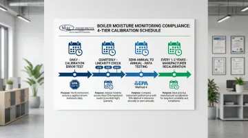
| Test Type | Frequency | Purpose |
|---|---|---|
| Calibration Error Test | Daily | Required for EPA Part 75; checks drift against reference gas |
| Linearity Check | Quarterly | Verifies accuracy at low, mid, and high measurement levels |
| RATA (Relative Accuracy Test) | Semi-Annual/Annual | Comparison against EPA Method 4 reference method |
| Manufacturer Recalibration | 1-2 Years | Factory recalibration for capacitive polymer sensors |
Perform field verification using reference methods or portable calibration equipment. At minimum, schedule calibration quarterly — but also trigger it after sensor cleaning or any process upset such as fuel switches or major load changes.
Analyzers with built-in calibration systems, like the MAC155, enable daily two-point in-situ checks without pulling sensors from service, which meaningfully tightens data quality assurance between scheduled events.
Ensure Proper Installation Location and Technique
Select measurement points where gas flow is uniform, temperature is stable, and moisture hasn't condensed:
- Location criteria: Minimum 8 duct diameters downstream and 2 diameters upstream of flow disturbances; avoid areas near air in-leakage or cool surfaces
- Insertion depth: Install at duct centerline for ducts under 24 inches; use EPA Method 4 traverse points for larger stacks
- Probe heating: Maintain probe temperature at least 20°F above water dew point but not exceeding 250°F to prevent sensor damage
- Heat tracing: Apply electrical heat tracing to sample lines maintaining temperatures above 120°C (248°F) to prevent condensation in extractive systems
Verify installation meets manufacturer specifications and regulatory requirements. Document probe location, insertion depth, and heating setpoints in your monitoring plan.
Maintain Sensors and Perform Routine Cleaning
Establish inspection intervals based on fuel type and combustion conditions:
- Coal/biomass operations: Monthly visual inspection; clean filters and sensor surfaces every 4-6 weeks
- Oil-fired systems: Bi-monthly inspection; clean quarterly or when pressure drop across filter exceeds 2 PSI
- Natural gas facilities: Quarterly inspection; annual cleaning typically sufficient
Cleaning Procedures:
- Gentle brushing with soft-bristle brush for particulate removal
- Solvent cleaning (isopropyl alcohol) for tar or oil deposits
- Follow manufacturer protocols exactly—aggressive cleaning damages sensor surfaces
- Replace 10-micron ceramic or sintered stainless filters when cleaning no longer restores flow
Replace consumable components on schedule: filters every 6-12 months, desiccants if applicable, and gaskets during annual maintenance. Consider automatic filter blow-back systems that use 10 PSI clean dry air to extend filter life in high-particulate applications.
Select Advanced Measurement Technology
Modern moisture analyzers with built-in calibration systems measurably reduce measurement errors. Look for these features:
Critical Technology Selection Criteria:
- Built-in calibration: Generates reference gases internally for daily verification — no external equipment needed
- NIST-traceable accuracy: Documented accuracy of ±1-2% of reading to support regulatory compliance
- High-temperature capability: Ratings to 1200°F standard (optional to 2400°F) eliminate sample conditioning and cooling requirements
- Solid-state design: No chemicals, compressed air, or optical components that degrade — fewer consumables, lower ongoing cost
- Contamination resistance: Protective filtration and corrosion-resistant materials (stainless steel, ceramic) extend sensor service life
Technologies like TDLAS (Tunable Diode Laser Absorption Spectroscopy) offer accuracy of ±1 ppmV with drift below 0.1 ppmV/year and no annual recalibration requirement. The upfront cost is higher than traditional sensors, but reduced maintenance intervals and long-term stability typically offset that gap within a few operating cycles in harsh boiler exhaust environments.
Tips for Long-Term Prevention and Control
Accurate moisture readings don't happen by accident — they're the result of consistent processes, well-trained operators, and the right equipment. These four practices form the foundation of a reliable long-term measurement program.
Documentation and Trending:
- Maintain calibration and maintenance records with trend analysis to predict drift patterns before they trigger compliance violations
- Track sensor performance metrics (response time, baseline stability, calibration adjustment magnitude) to identify degradation early
- Document all fuel switches, process upsets, and maintenance activities that correlate with measurement changes
Cross-Verification Methods:
- Compare moisture readings against alternative methods during annual compliance testing (portable analyzers, EPA Method 4 gravimetric)
- Use psychrometric calculations based on stack temperature and oxygen measurements to verify moisture values
- Employ wet/dry oxygen comparison where both measurements exist—significant deviation indicates analyzer problems
Operator Training and Competency:
- Train operators on interpreting readings and recognizing abnormal values that indicate sensor problems
- Educate staff on the relationship between combustion conditions (excess air, fuel moisture content) and expected moisture levels
- Establish clear escalation procedures when readings fall outside expected ranges
Upgrade to Purpose-Built Analyzers:
- Sensors designed specifically for high-temperature flue gas environments (rated to 1200°F or higher) resist contamination better than general-purpose alternatives
- NEMA 4X weatherproof enclosures handle outdoor stack installations across wide ambient temperature swings (-40°F to 120°F)
- Built-in calibration systems allow daily verification without interrupting the process — a key advantage during continuous emissions monitoring
Conclusion
Inaccurate boiler exhaust moisture readings trace back to four identifiable root causes:
- Sensor contamination from combustion byproducts
- Calibration drift from thermal cycling and corrosive gases
- Installation errors that create localized measurement biases
- Temperature-related issues that cause condensation or sensor damage
Each is preventable with the right equipment, installation practices, and maintenance schedule.
Proper equipment selection, correct installation, and routine calibration keep measurements reliable — and directly improve combustion efficiency and regulatory compliance. Facilities with systematic moisture management programs reduce fuel waste, avoid EPA penalties, and prevent costly equipment damage.
The numbers make a clear case: efficiency improvements of just 0.29% can deliver over $200,000 in annual savings for mid-sized generators. Avoiding EPA missing data substitution penalties eliminates the additional risk of artificially inflated emissions reporting.
Frequently Asked Questions
How much steam should come out of a boiler vent?
Visible steam varies with ambient conditions — cold weather makes water vapor visible even during normal operation. Excessive or continuous steam may indicate faulty pressure relief valves, steam trap failures, or venting issues that warrant investigation.
What is condensation of natural gas exhaust?
Natural gas combustion produces water vapor from the hydrogen in the fuel. This vapor condenses when cooled below its dew point — typically 120-130°F at atmospheric pressure — and moisture that condenses before reaching the analyzer produces falsely low readings.
How often should boiler exhaust moisture sensors be calibrated?
EPA Part 75 requires quarterly linearity checks and semi-annual or annual RATA testing depending on performance. Best practice recommends quarterly calibration as a minimum, with monthly verification for harsh conditions or critical compliance applications.
What is the typical accuracy range for industrial moisture analyzers?
Industrial moisture analyzers typically achieve ±1-2% of moisture by volume full scale accuracy. TDLAS technology provides ±1 ppmV or ±3% of reading, while capacitive polymer sensors offer ±2°C dew point accuracy. NIST-traceable systems provide the documented accuracy required for regulatory compliance.
Can I use multiple measurement methods to verify moisture readings?
Yes. Cross-verification using EPA Method 4 gravimetric testing, psychrometric calculations, or portable analyzers validates installed system accuracy. Perform cross-checks during annual compliance testing and whenever readings deviate significantly from expected values.
What causes sudden drops in measured moisture content?
The most common causes include:
- Air in-leakage diluting exhaust gases
- Probe heating failure causing condensation ahead of the sensor
- Sensor contamination creating an insulating barrier
- Process changes such as reduced fuel moisture or lower combustion air humidity
Investigate any drop exceeding 2% by checking probe temperature, inspecting for duct leaks, and confirming fuel and operating conditions are unchanged.