Introduction: The Hidden Cost of Moisture Measurement Mistakes
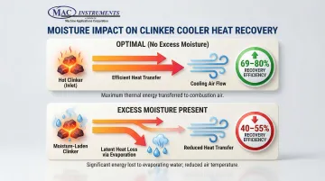
Misplaced moisture sensors cost cement plants thousands of dollars a day. Every percentage point of uncontrolled moisture drives up fuel consumption directly, and cooler heat recovery efficiency — typically 69-80% — drops whenever moisture disrupts the enthalpy balance.
Most facilities treat moisture measurement as a one-size-fits-all challenge. Cooler-rated equipment installed in 2,400°F kiln zones fails prematurely. Kiln-grade sensors deployed where they're unnecessary add unnecessary cost. Either way, measurement drift of 10-15% corrupts the process data that operators rely on.
That data quality gap also has a regulatory dimension. Under 40 CFR 63.1343, accurate moisture measurement is a federal compliance requirement for emissions reporting — not a best practice.
This guide clarifies the critical differences between kiln discharge and clinker cooler measurement environments, reveals the five most expensive mistakes cement plants make, and provides a practical decision framework for selecting the right technology for each location.
TLDR: Key Takeaways
- Kiln discharge (2,400°F) and clinker cooler (200-400°F) zones require different sensor technologies; one solution cannot serve both
- Wrong-temperature equipment fails fast: cooler-rated sensors burn out in kilns, over-specced units waste capital in moderate zones
- Uncompensated temperature drift causes 10-15% measurement errors, triggering incorrect process adjustments and fuel waste
- Built-in calibration and NIST-traceable accuracy eliminate drift and satisfy EPA compliance requirements
- Match sensor technology to zone temperature to protect fuel efficiency, clinker quality, and regulatory standing
Understanding Moisture's Role in Cement Quality
Moisture content affects energy use, product quality, and emissions at every stage of cement production. During clinker formation, excess moisture requires additional thermal energy for evaporation before calcination can occur. This thermodynamic burden diverts heat from the 1,450°C sintering zone, forcing higher fuel input to maintain burning temperature and reducing kiln thermal efficiency.
The relationship between moisture and energy consumption is direct and unforgiving. Water vaporization consumes heat that should drive the chemical reactions forming alite (tricalcium silicate), the primary compound responsible for cement's hardening properties.
When moisture levels vary unpredictably, operators cannot optimize fuel input. The result is either excessive energy consumption or incomplete clinker formation — both of which compromise final product strength.
In the clinker cooler, moisture impacts heat recovery performance and equipment longevity. Modern grate coolers achieve heat recovery efficiencies between 69% and 80% by transferring sensible heat from hot clinker into secondary and tertiary combustion air. However, moisture in the clinker bed alters this enthalpy balance — heat that should be recuperated is instead consumed evaporating water or lost if the cooling profile becomes disrupted. A published analysis in PMC found that optimizing cooler operating parameters can save approximately 10% in electric energy consumption, with moisture control being a key variable.
Beyond energy efficiency, moisture measurement is a regulatory imperative. Key compliance requirements include:
- US EPA 40 CFR 63.1343 requires cement facilities to apply appropriate moisture corrections when measuring flow rates for mercury and particulate matter
- CEMS integration must incorporate real-time moisture data — gaps in this data create direct compliance risk
- Facilities that skip accurate moisture correction face potential operating license violations
The Critical Difference: Kiln vs Clinker Cooler Environments
Kiln Environment Challenges
The kiln discharge zone presents the most extreme measurement conditions in cement manufacturing. Material exits the kiln at approximately 1,200°C (2,200°F), with gas temperatures often exceeding 2,400°F. This thermal environment immediately disqualifies most industrial sensors and requires specialized high-temperature measurement principles.
Key challenges include:
- Standard electronics cannot survive radiated heat from 1,200°C clinker — remote-mounted electronics and thermal shielding are required
- Calcined material has different dielectric properties than raw feed, creating distinct challenges for moisture measurement at this stage
- Exhaust gases — including SO₂, NOx, and HCl — demand corrosion-resistant housings made from stainless steel or ceramic
- Dust loads are significant enough that plants must meet emission limits of 0.02–0.07 lb/ton of clinker, requiring active sensor purge systems to prevent fouling
Clinker Cooler Environment Challenges
The clinker cooler operates in a dramatically different thermal regime, with temperatures dropping from kiln discharge levels to a target exit range of 100–200°C (200–400°F). However, this "cooler" environment introduces its own measurement complexities.
Specific challenges include:
- Hot spots persist throughout the cooler bed, requiring sensors rated to 400°C (752°F) to handle surges and process upsets
- Grate coolers force cold air through the clinker bed at 55–80 mbar, creating turbulent conditions that interfere with technologies relying on thermal conductivity or convection principles
- Clinker nodules of 10–25 mm form across bed depths of 0.4–1.3 meters, so single-point measurements often fail to represent bulk moisture content
- Optical and NIR sensors are prone to rapid fouling from dust accumulation, requiring continuous purge air to maintain accuracy
Why Measurement Location Matters
These two environments don't just require different sensors — they serve different control purposes entirely. Pre-cooler readings at the kiln discharge inform kiln operation decisions: fuel input, raw meal feed rates, and kiln speed. Post-cooler readings affect downstream operations — grinding efficiency, cement quality, and storage conditions.
Installing sensors at the wrong location creates a control feedback mismatch. A sensor measuring cooler discharge moisture cannot provide the rapid feedback needed for kiln optimization, while a kiln discharge sensor offers no insight into cooler performance or secondary air quality. That location gap shifts control from predictive to reactive, driving up energy consumption and quality variability.

The Top 5 Mistakes Cement Plants Make
Mistake #1: Using Temperature-Inappropriate Equipment
Installing cooler-rated equipment in kiln environments — or vice versa — ranks as the costliest sensor mistake in cement plants. Standard industrial moisture sensors max out at 120-200°C, yet kiln discharge conditions routinely hit 1,200°C+. The failure modes follow a predictable pattern.
Consequences include:
- Electronics fail within hours when exposed to radiated heat beyond the sensor's rated limit
- Thermal shock fractures optical windows, causing complete measurement loss
- Sensors beyond their temperature rating drift rapidly, generating false readings that trigger incorrect process adjustments
- Replacement cycles compress from multi-year service life down to every 3-6 months
The reverse mistake—over-specifying equipment—wastes capital. Installing 2,400°F-rated sensors in 200°F cooler discharge zones provides no performance benefit while increasing equipment costs by 2-3x compared to appropriately rated alternatives.
Mistake #2: Ignoring Ambient Temperature Compensation
Temperature variations cause significant measurement errors that compound over time. Application notes confirm that even slight temperature differences produce significant errors in moisture readings. Without real-time compensation, seasonal and daily temperature swings can push readings 10-15% off target.
The drift develops slowly, which makes it dangerous. Operators keep adjusting process parameters against readings that quietly diverge from actual conditions. Within weeks or months, the plant is running on bad data, leading to:
- Fuel overconsumption as operators compensate for perceived moisture that doesn't exist
- Quality issues when actual moisture exceeds what sensors report
- Failed calibration verifications that require expensive recalibration or sensor replacement
Sensors with built-in automatic temperature compensation eliminate this drift by continuously correcting for ambient variations — maintaining accuracy through seasonal changes and daily temperature cycles alike.
Mistake #3: Poor Sensor Placement and Installation
Even the right sensor fails if installed in the wrong location. Cement plants frequently mount sensors in dead zones where material flow is minimal, in areas prone to material buildup, or in dust concentration points that rapidly foul optical elements.
Optimal placement requires:
- Mounting where material flow is continuous and representative of bulk conditions — not in dead zones
- Selecting locations where material doesn't accumulate on sensor surfaces or mounting hardware
- Positioning away from primary dust streams while still sampling representative gas or material flows
- Installing where maintenance, calibration, and cleaning are accessible without production shutdowns
Single-point measurements work only when the measurement location is truly representative. In clinker coolers with bed depths varying from 0.4 to 1.3 meters and heterogeneous particle size distribution, multiple measurement points or averaging technologies may be necessary for accurate bulk moisture determination.
Mistake #4: Selecting the Wrong Measurement Principle
Moisture measurement technologies operate on fundamentally different physical principles, and no single approach excels in all environments. Forcing a familiar technology into an incompatible application guarantees unreliable data — regardless of how well the sensor is installed or maintained.
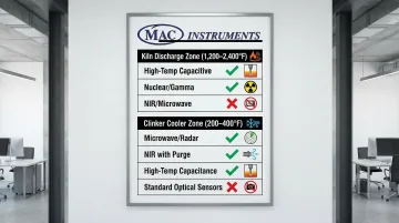
Technology suitability by location:
Kiln Discharge (1,200-2,400°F):
- High-temperature capacitive sensors: Measure dielectric property changes caused by water vapor, operate to 2,400°F with proper mounting
- Nuclear/Gamma: Unaffected by temperature or chemical properties, ideal for non-intrusive measurement in extreme conditions
- NOT suitable: Standard microwave, NIR, or low-temperature capacitance probes
Clinker Cooler (200-400°F):
- Microwave/Radar: Excellent for bulk measurement, handles densities from 0.8 to 2.0 g/cm³, available with cooling for up to 450°C
- NIR (Near-Infrared): Good for conveyor discharge points with proper dust management and cooling jackets
- High-temperature capacitance: Rated specifically for up to 400°C, robust for in-bed measurement
- NOT suitable: Technologies requiring optical clarity without active purging
A NIR sensor without purge air in a dusty cooler will foul within weeks. A standard capacitance probe at kiln discharge fails outright. Technology selection sets the ceiling on what any installation can achieve.
Mistake #5: Inadequate Maintenance and Calibration Protocols
All sensors drift. The only variable is whether you catch and correct it before it affects operations — or after it already has.
Drift accumulation leads to:
- Major process inefficiencies as control systems respond to inaccurate data
- Energy waste from fuel input adjustments based on false moisture readings
- Quality variability when actual moisture deviates from sensor readings
- Compliance risks if emissions calculations use uncalibrated moisture data
Calibration frequency must match the technology type and measurement location. Contact sensors in harsh environments need more frequent verification than non-contact technologies. High-temperature applications accelerate drift faster than moderate-temperature installations. Base calibration schedules on:
- Sensor technology — optical sensors may need monthly cleaning verification; solid-state sensors quarterly calibration checks
- Environmental severity — kiln discharge sensors require more frequent validation than cooler discharge sensors
- Regulatory requirements — EPA compliance applications demand documented calibration protocols with specific frequencies
- Process criticality — sensors controlling primary process variables need tighter calibration intervals than monitoring-only applications
Choosing the Right Measurement Technology
Technology Comparison Matrix
Selecting the optimal moisture measurement technology requires matching sensor capabilities to specific process conditions. No single technology excels across all parameters—the best choice depends on temperature range, accuracy requirements, material characteristics, maintenance resources, and budget constraints.
| Technology | Temperature Range | Accuracy | Kiln Suitable | Cooler Suitable | Maintenance Level | Relative Cost |
|---|---|---|---|---|---|---|
| High-Temp Capacitive | Up to 2,400°F | ±1% | Excellent | Excellent | Low | Moderate |
| Microwave/Radar | Up to 450°F | ±0.1% | No | Excellent | Low | Moderate-High |
| NIR (Near-Infrared) | Up to 300°F* | ±0.5% | No | Good | Moderate-High | Moderate |
| Nuclear/Gamma | Unlimited | ±1-2% | Excellent | Good | Very Low | High |
*With cooling jacket
Key Selection Criteria
Three factors should drive every technology decision:
- Temperature capability: Verify peak and average temperatures at the measurement point, then select sensors rated at least 100°F (50°C) above maximum expected temperatures. Kiln discharge applications running at 1,200°C disqualify standard industrial sensors outright.
- Response time: Process control applications need sensors that reach 90% of final value within 60–120 seconds. Monitoring-only applications, where data is used for trending, can tolerate response times of several minutes.
- Accuracy and repeatability: Match sensor specifications to actual control requirements. If fuel optimization requires moisture control within ±0.5%, a sensor rated at ±2% won't deliver the needed precision — but over-specifying accuracy adds cost without operational benefit.
For kiln and cooler applications specifically, MAC Instruments' MAC125 and MAC155 analyzers are built around these criteria — rated to 2,400°F, using solid-state technology with no chemicals or optical components, and delivering 60–120 second response times with NIST-traceable accuracy. Built-in automatic temperature compensation keeps readings stable without manual recalibration.
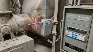
Installation and Integration Considerations
High-temperature environments demand specialized mounting hardware. Standard threaded fittings and flanges cannot withstand 2,400°F process temperatures—installations require ceramic protection tubes, water-cooled jackets, or retractable mounting systems that allow sensor withdrawal during maintenance without process shutdown.
Integration with DCS/SCADA systems requires temperature-compensated 4-20mA outputs that maintain accuracy across the full operating range. Analog signals provide excellent noise immunity for the long cable runs typical in cement plants. Digital protocols like HART or Modbus add remote diagnostics and predictive maintenance capabilities. Modern systems should support remote access through secure gateways, allowing troubleshooting independent of the primary control system.
Best Practices for Implementation
Site Assessment Before Equipment Selection
Before selecting equipment, measure actual temperatures at the proposed installation point across multiple operating conditions — peak, average, and minimum. Document dust levels, access constraints, and available utilities (compressed air, electrical power, cooling water). Confirm that mounting locations provide representative sampling while allowing safe maintenance access.
Baseline Validation During Commissioning
Use laboratory analysis during commissioning to validate in-line sensor readings before trusting them for process control. Collect manual samples simultaneously with sensor measurements and compare results using standard methods:
- Oven-dry analysis or Loss on Ignition (LOI) for gravimetric verification
- Side-by-side comparison at multiple moisture levels to confirm accuracy across the operating range
- Documentation of any offsets or calibration adjustments made at installation
This step catches installation and calibration issues early, when corrections are straightforward.
Preventive Maintenance Schedule
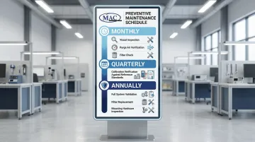
Maintenance frequency depends on technology type and environmental severity. High-temperature, dusty applications — like kiln exhaust measurement — demand more attention than moderate-temperature installations. A typical schedule looks like this:
- Monthly: Visual inspection, purge air system verification, filter condition check
- Quarterly: Calibration verification against reference standards or manual samples
- Annually: Complete system validation, filter replacement, mounting hardware inspection
Frequently Asked Questions
Frequently Asked Questions
How do you measure moisture content in a clinker cooler?
Clinker cooler moisture measurement uses non-contact technologies—microwave absorption sensors or near-infrared analyzers—mounted above the cooler bed. These sensors operate at 200–400°F and must account for cooling air effects and bed depth variations, typically requiring multiple measurement points for a representative reading.
What equipment is used to measure moisture content in a clinker cooler?
Common options include microwave absorption sensors, near-infrared reflectance analyzers, and high-temperature capacitance probes rated to 400°F. All equipment must handle dust accumulation and continuous thermal cycling—stainless steel or ceramic construction with active purge systems is standard for long-term reliability in this environment.
Does temperature affect moisture meter readings in a clinker cooler?
Yes. Sensors without built-in temperature compensation can drift 10–15% across the temperature swings—often 100°C or more—between cooler zones. Automatic temperature correction and periodic calibration checks are essential for maintaining accuracy.
How do you calculate clinker cooler efficiency?
Cooler efficiency equals heat recovered divided by heat input, expressed as a percentage. Heat input is the sensible heat of clinker entering from the kiln; heat recovered is the heat transferred to secondary and tertiary combustion air. Moisture content is a key variable because energy used to evaporate water reduces calculated efficiency—that heat is not recovered into combustion air.