Introduction
Moisture measurement errors can bias reported pollutant concentrations by up to 30% for NO₂ and 20% for SO₂—enough to trigger false compliance violations or misreport your facility's emissions. Since regulatory agencies require emissions on a dry basis, even small measurement inaccuracies carry through directly to final reported data.
Accurate stack moisture measurement is fundamental to both regulatory compliance and reliable emissions calculations.
Facilities face strict measurement uncertainty requirements under EPA and EU regulations, with continuous monitoring or approved alternatives required for most sources.
This article compares three primary moisture measurement approaches and explains their compliance applications:
- Condensation-based extractive sampling
- In-situ capacitive sensors
- Chilled mirror and wet bulb techniques
You'll learn how each method works, when to use it, and how to interpret results accurately for regulatory reporting.
TLDR
- Measurement errors cause 20-30% bias in emissions reporting
- Three main methods: condensation/extractive, in-situ capacitive, and chilled mirror/wet bulb
- Regulations require <2.5% uncertainty (high-emission) or <7.5% (lower-emission)
- Daily calibration checks required, with quarterly reference method verification
- Method selection depends on temperature: extractive to 400°F, in-situ capacitive to 2400°F
What You Need to Measure Stack Moisture for Emissions Compliance
Regulatory requirements drive every aspect of moisture measurement system selection. Compliance frameworks specify three primary moisture accounting methods:
- Continuous monitoring systems (EPA 40 CFR Part 75 for SO₂ dry basis reporting)
- Fuel-specific default values or psychrometric charts for saturated streams
- Physical sample gas drying before analysis (EU Industrial Emissions Directive option)
Selecting the right approach depends on your facility's emission level, fuel type, and regional requirements.
Regulatory and Technical Requirements
Measurement uncertainty thresholds vary by facility emission level. The EU ETS establishes tiered uncertainty limits: 2.5% for Tier 4 (highest emission sources), 5% for Tier 3, 7.5% for Tier 2, and 10% for Tier 1.
In the U.S., facilities emitting 25,000 metric tons CO₂e or more annually fall under mandatory greenhouse gas reporting (40 CFR Part 98), subjecting them to more rigorous monitoring requirements including site-specific moisture determinations when not using continuous monitors.
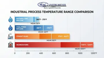
Beyond regulatory compliance, stack gas temperature determines which measurement technologies can physically operate in your environment:
- Natural gas boilers: 280-370°F (mean ~310°F)
- Coal-fired boilers: 285-590°F (mean ~450°F)
- Cement kilns (dry process): 375-845°F (mean ~555°F)
- Incinerators: 700-1200°F (pathological avg. 1000°F)
- Specialized processes: Up to 2400°F requiring high-temperature capable equipment
Environmental and Access Considerations
Stack accessibility requirements extend beyond physical platform safety. EPA Method 1 mandates proper traverse point selection to ensure representative measurements:
- Circular stacks >24 inches: Minimum 12 traverse points required
- Circular stacks 12-24 inches: Minimum 8 traverse points required
- Wall clearance: No traverse points within 1 inch of stack walls for stacks >24 inches diameter
Sampling locations must avoid stratified flow zones, moisture injection points, and turbulent areas.
Method 1 requires verification that cyclonic flow is absent—if the average gas flow rotation angle exceeds 20°, the location is unacceptable for standard testing.
Methods to Measure Stack Moisture for Emissions Compliance
Three primary measurement approaches exist, each optimized for specific temperature conditions, accuracy requirements, and operational constraints.
Method 1: Condensation-Based Extractive Sampling
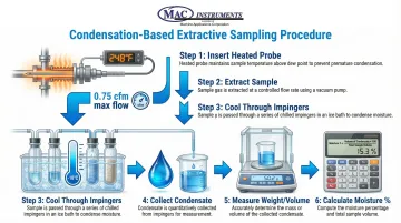
Description: This reference method extracts a gas sample from the stack, cools it through an impinger train to condense moisture, then measures the collected water gravimetrically or volumetrically. EPA Method 4 is the primary reference standard, while Method 5 (particulate sampling) serves as an acceptable alternative for moisture determination.
Equipment and Process: The sampling train consists of a heated probe, optional heated filter, and four impingers arranged in series. The first two impingers contain water, the third remains empty to catch carryover, and the fourth contains silica gel as a final desiccant.
The probe and filter must maintain approximately 120°C (248°F) to prevent premature condensation that would bias results low.
Step-by-Step Process:
- Insert heated probe at proper traverse point per EPA Method 1
- Extract sample at constant rate (maximum 0.75 cfm) through heated sample line
- Cool gas through impinger series submerged in ice bath
- Collect condensed moisture in impingers
- Measure condensate weight and total sample volume
- Calculate moisture percentage: (weight of water collected / total sample volume) × 100
Advantages: This method excels when integrated with particulate sampling (EPA Method 5) and provides legally defensible reference data.
Limitations: It's time-intensive (typically 60-120 minutes per test), requires skilled technicians, and risks sample loss through inadequate heating or leaks. High-moisture streams (>20%) can overwhelm impinger capacity, and the 21 scf minimum sample volume makes continuous monitoring impractical.
Method 2: In-Situ Capacitive Sensor Technology
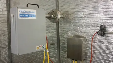
Description: Capacitive sensors measure moisture directly in the stack by detecting changes in capacitance caused by water vapor partial pressure. Unlike extractive methods, these sensors install permanently in the gas stream for continuous real-time monitoring. MAC Instruments' MAC155 uses patented capacitive technology that responds directly to water vapor pressure without requiring chemicals, compressed air, or optical components.
Equipment and Process: The system consists of a high-temperature capacitive probe mounted directly in the flue gas stream, a NEMA 4X weatherproof analyzer housing, and integrated electronics for signal processing. The MAC155 operates continuously at temperatures up to 1200°F (650°C) standard, with optional capability to 2400°F (1300°C).
The built-in calibration system contains a 17 fl. oz. distilled water tank that generates reference vapor samples for daily two-point calibration verification, using only 17 oz. of water annually.
Step-by-Step Process:
- Install probe at proper traverse point through stack wall
- Allow sensor to reach thermal equilibrium with stack gas (typically 60 seconds)
- Sensor continuously measures capacitance changes caused by water vapor
- Electronics automatically convert capacitance to moisture percentage
- Output 4-20mA signal to data acquisition system for compliance reporting
- Perform daily automated calibration checks using built-in system
Advantages:
- Excels for continuous monitoring and high-temperature applications where extractive methods fail
- Provides NIST-traceable accuracy of ±1% of full scale with 60-second response time
- Requires no consumables or chemicals
- Minimizes maintenance through solid-state design
- Built-in calibration system ensures EPA compliance without external equipment
Limitations: Initial investment is higher than manual methods, though operational costs are lower due to minimal maintenance and no consumables.
Method 3: Chilled Mirror and Wet Bulb Techniques
Description: These traditional methods determine moisture content indirectly. Chilled mirror hygrometers measure dew point by gradually cooling a reflective surface until condensation forms, then calculate moisture from dew point and stack temperature. Wet bulb techniques use psychrometric principles, measuring the temperature difference between wetted and dry thermocouples to determine relative humidity.
Equipment and Process: Chilled mirror systems require extractive sampling with controlled cooling of a mirror surface and optical detection of condensation onset. Wet bulb systems insert dual temperature probes (one with wetted wick, one dry) directly into the gas stream or use extracted samples.
Step-by-Step Process:
For chilled mirror:
- Extract gas sample through heated line
- Direct sample across temperature-controlled mirror surface
- Gradually cool mirror while monitoring with optical detector
- Record temperature when condensation first appears (dew point)
- Calculate moisture content from dew point and stack temperature using psychrometric tables
For wet bulb:
- Insert wet and dry temperature probes at measurement location
- Ensure wetted wick remains saturated with distilled water
- Measure temperature difference between probes
- Apply psychrometric calculations or charts to determine moisture content
Advantages: These methods work well for lower-temperature applications (<400°F) and periodic verification testing. EPA 40 CFR § 75.11(b) permits psychrometric charts for saturated gas streams following wet scrubbers.
Limitations:
- Chilled mirrors are susceptible to contamination from particulates or condensable organics, requiring frequent cleaning
- Wet bulb measurements demand constant wick maintenance and fresh water supply
- Neither method suits high-temperature continuous monitoring
- Both introduce potential errors from improper wick saturation or mirror contamination
How to Interpret Moisture Measurement Results for Compliance
Proper interpretation of moisture measurements is critical because errors directly impact reported emissions concentrations and can trigger compliance violations or incorrect emissions trading calculations.
Understanding Moisture Content Ranges
Typical moisture content varies significantly by fuel type and combustion process:
| Fuel Type | Moisture Range | EPA Default (if applicable) |
|---|---|---|
| Natural gas combustion | 10-20% | 14.0% for boilers |
| Coal - Anthracite | ~3.0% | 3.0% |
| Coal - Bituminous | ~6.0% | 6.0% |
| Coal - Sub-bituminous | ~8.0% | 8.0% |
| Coal - Lignite | ~11.0% | 11.0% |
| Wood/biomass combustion | 13-15% | 13.0% |
| Waste incineration | 15-25% | — |
Values outside these ranges require investigation.
Unusually low readings may indicate condensation in sample lines or sensor drift. High readings could signal water injection, scrubber carryover, or measurement errors.
Calculating Dry Basis Emissions Concentrations
Pollutant concentrations measured on a wet basis must be converted to dry basis for regulatory reporting.
The standard EPA Method 4 formula is:
C_dry = C_wet / (1 - B_ws)
Where:
- C_dry = pollutant concentration on dry basis
- C_wet = pollutant concentration on wet basis
- B_ws = water vapor fraction by volume (expressed as decimal)
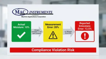
Example: A facility measures 150 ppm SO₂ on a wet basis with 10% moisture (B_ws = 0.10):
- C_dry = 150 / (1 - 0.10) = 150 / 0.90 = 167 ppm
If moisture measurement is incorrect at 20% instead of 10%:
- C_dry = 150 / (1 - 0.20) = 150 / 0.80 = 188 ppm
This 10% moisture measurement error creates a 12.5% error in reported emissions—potentially the difference between compliance and violation.
Meeting Measurement Uncertainty Requirements
EU ETS regulations impose strict uncertainty thresholds based on facility emission levels:
| Facility Emission Level | Maximum Uncertainty |
|---|---|
| High (>25,000 tons CO₂/year) | <2.5% |
| Lower (≤25,000 tons CO₂/year) | <7.5% |
Verify your measurement system meets these requirements through:
- Daily calibration drift checks: Zero and span verification within ±2% of reference values
- Quarterly audits: Relative Accuracy Test Audits (RATA) comparing continuous monitors to reference methods
- Annual verification: EU EN 14181 requires Annual Surveillance Tests with minimum 5 parallel measurements against Standard Reference Methods
High-precision instruments with NIST-traceable calibration—such as those from specialized manufacturers like MAC Instruments—help facilities maintain these strict uncertainty requirements consistently.
Identifying Measurement Issues
Warning signs of problematic moisture measurements include:
- Out-of-range values — Moisture readings inconsistent with fuel type (e.g., 25% moisture from natural gas combustion)
- Significant variations during steady-state operation indicate sensor instability or sampling issues
- Mass balance discrepancies: Moisture values that don't align with combustion calculations based on fuel analysis and excess air
- Failing daily drift checks or quarterly audits signals sensor degradation requiring recalibration or replacement
When these issues arise, investigate potential causes:
- Condensation in sample lines (verify heating maintains temperature 20-30°F above stack temperature)
- Sensor contamination from particulates or chemical exposure
- Calibration drift requiring adjustment or sensor replacement
Common Errors in Stack Moisture Measurement
Several systematic errors reduce moisture measurement accuracy and create regulatory compliance risks.
Condensation in Sample Lines and Probes: Inadequate heating of extractive sampling systems causes moisture to condense before measurement, resulting in artificially low readings. Both EPA Method 4 and EN 14790 require specific temperature thresholds:
- Probe and filter temperatures: approximately 120°C (248°F)
- Alternative threshold: 20°C above acid dew point (whichever is greater)
- Heat tracing must extend from probe tip through entire sample line
Condensation losses lead to under-reporting moisture, which causes over-reporting of dry-basis pollutant concentrations—potentially triggering false compliance violations.
Improper Calibration and Verification: Continuous monitoring systems experience inevitable calibration drift. EPA 40 CFR Part 60 Appendix F requires daily calibration drift checks at zero and high-level points, with acceptable drift limits typically ±2% of span.
Quarterly Relative Accuracy Test Audits (RATA) compare continuous monitors to reference methods, with acceptance criteria typically requiring agreement within ±20% relative accuracy. Facilities that skip calibration procedures or ignore drift warnings accumulate measurement error that invalidates compliance data.
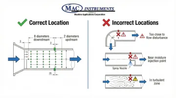
Incorrect Sampling Location: Sampling at locations with stratified flow, near moisture injection points, or in turbulent zones produces non-representative measurements. EPA Method 1 specifies minimum distances from flow disturbances: at least 8 stack diameters downstream and 2 diameters upstream from any flow disturbance.
Traverse point selection must follow Method 1 requirements to ensure measurements represent the average stack conditions, not localized anomalies.
Regulatory Compliance and Best Practices
Regulatory acceptance depends on following proper measurement protocols and maintaining thorough documentation. Understanding these requirements helps facilities avoid compliance issues and costly re-testing.
Quality Assurance Requirements
Essential QA/QC procedures ensure measurement accuracy and regulatory acceptance:
- Daily calibration checks (zero and span verification)
- Quarterly cylinder gas audits for extractive methods
- Comprehensive documentation for all testing and corrective actions
EPA Performance Specification 4B requires continuous monitors to maintain calibration drift within specified limits and pass quarterly RATAs. Documentation must include all out-of-control periods, corrective actions taken, and results of all audits and assessments.
Maintenance and Calibration Schedules
Calibration intervals vary by technology:
- Daily: Zero and span calibration drift checks for continuous monitors
- Quarterly: Calibration verification using reference methods (RATA or cylinder gas audit)
- Annually: Complete system audit and Annual Surveillance Test (EU EN 14181)
- Before each test: Equipment calibration verification for periodic extractive sampling
MAC Instruments' in-situ capacitive sensors simplify these requirements. The MAC155 includes a built-in calibration system that performs automated daily two-point checks without external equipment or service interruptions, reducing maintenance time and labor costs.
Integration with CEMS
Moisture measurement connects to overall continuous emissions monitoring systems through standard 4-20mA analog outputs for automated compliance reporting.
Modern systems include:
- Data validation algorithms
- Alarm functions for out-of-range conditions
- Automated calculation of dry-basis concentrations
- Sensor signal substitution for total system verification
The MAC155's system calibration features verify the entire measurement chain from sensor to data acquisition. This ensures all components function correctly for regulatory reporting.
Frequently Asked Questions
How to measure moisture content in gas?
Three primary approaches exist: extractive condensation methods (EPA Method 4) collect and weigh condensed moisture through impinger trains. In-situ sensors measure moisture directly in the gas stream using capacitance or optical techniques. Dew point methods determine moisture from condensation temperature using chilled mirrors or psychrometric calculations.
Why is moisture measurement critical for emissions compliance?
Pollutant concentrations must be reported on a dry basis, making accurate moisture measurement essential for correct conversion calculations. A 10% moisture measurement error creates approximately 12% error in reported pollutant concentrations, potentially causing compliance violations.
What is the required measurement uncertainty for stack moisture monitoring?
EPA and EU regulations typically require measurement uncertainty below 2.5% for high-emission facilities (>25,000 tons CO₂/year) and below 7.5% for lower-emission sources. Requirements vary by jurisdiction, with EU ETS establishing four tiers ranging from 2.5% to 10%.
What are the main differences between extractive and in-situ moisture measurement?
Extractive methods remove a gas sample for external analysis, requiring heated probes at 250°F (120°C) to prevent condensation but risking moisture loss in sample lines. In-situ methods measure directly in the stack, avoiding sampling artifacts while providing continuous real-time data ideal for high-temperature applications.
How often should stack moisture analyzers be calibrated?
Continuous monitors require daily zero and span checks with quarterly calibration verifications using reference methods (RATA or cylinder gas audits). The MAC155's built-in calibration system automates daily two-point verification, using only 17 oz. of distilled water annually.
What temperature ranges do different moisture measurement methods support?
Extractive condensation methods work best below 400°F due to sample line heating limitations, while chilled mirror and wet bulb techniques are limited to moderate temperatures. The MAC155 operates continuously at temperatures up to 1200°F standard, with optional capability to 2400°F for high-temperature applications.