Introduction
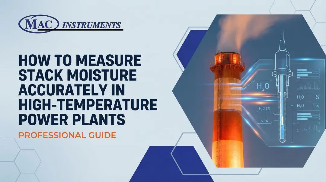
Flue gas moisture in waste-to-energy (WTE) plants is one of the most consequential variables operators deal with — yet it's among the hardest to measure accurately. Moisture content typically runs 10–25% by volume, directly affecting heat recovery efficiency, emissions compliance, and the longevity of downstream equipment.
The operational stakes are concrete. Elevated moisture levels can depress flue gas temperatures by up to 140 K (252°F), cutting steam production significantly. When that moisture combines with acid gases, condensation accelerates corrosion in economizers and baghouses — turning a measurement gap into a maintenance cost.
This article covers methods for measuring flue gas moisture, the equipment required, step-by-step procedures, and how to interpret results for operational decision-making in WTE facilities.
Key Takeaways
- Flue gas moisture in WTE plants typically ranges 10–25% by volume, directly affecting combustion efficiency and emissions control
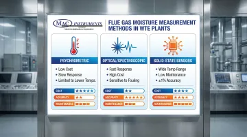
- Three measurement methods apply: psychrometric, optical/spectroscopic, and solid-state sensors — each with distinct accuracy, cost, and maintenance trade-offs
- Keep sample lines heated above 120°C, place sensors at least 8 duct diameters from flow disturbances, and calibrate regularly
- Deviations exceeding 5% from baseline signal combustion issues, air infiltration, or equipment problems requiring immediate investigation
- Most measurement failures trace to sample line condensation, poor sensor placement, or missing temperature and pressure compensation
What You Need to Measure Moisture in WTE Flue Gas
WTE flue gas pushes instruments hard — temperatures regularly exceed 1200°F, and corrosive acid gases accelerate sensor degradation. Getting reliable moisture readings means matching your equipment to those conditions and placing sampling points where the gas is actually representative.
Tools and Equipment Required
Measurement Instruments:
- Psychrometric equipment (wet/dry bulb thermometers or hygrometers) — limited applicability in WTE due to temperature constraints
- Optical analyzers — tunable diode laser absorption spectroscopy (TDLAS) or Fourier transform infrared (FTIR) systems
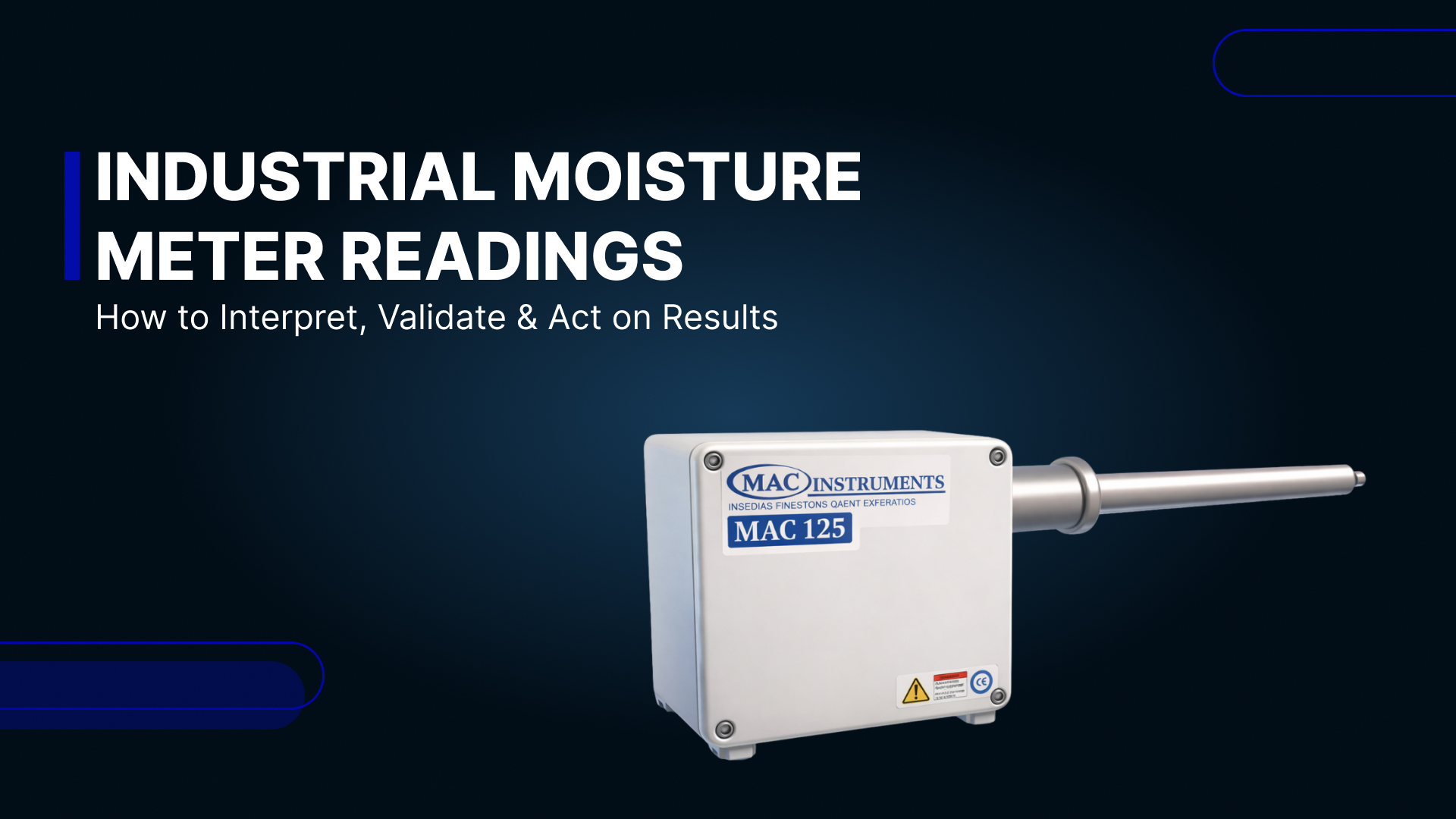
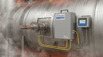
- Solid-state moisture sensors — the MAC Instruments MAC155 operates up to 1200°F standard (2400°F optional) with a built-in calibration system, requiring no chemicals, optics, or compressed air
- Sample conditioning systems for extractive measurement methods
- Data loggers — digital recorders with 4-20mA input capability
Each instrument type involves different tradeoffs in installation complexity, maintenance burden, and accuracy under high-temperature conditions. Solid-state analyzers generally require the least ongoing maintenance in WTE environments.
Supporting Equipment:
- Heated sample lines — maintain at least 248°F (120°C); 374°F (191°C) recommended for multi-pollutant streams to prevent condensation
- Temperature sensors for compensation calculations and accurate moisture determination
- Flow meters to verify isokinetic sampling conditions
- Calibration standards — NIST-traceable reference gases or built-in calibration systems
Sampling Location and Access Requirements
Optimal Sampling Points:
- Downstream of the combustion chamber but upstream of wet scrubbers, to capture representative flue gas composition
- At least 8 duct diameters downstream and 2 diameters upstream from flow disturbances (bends, dampers, fans) per EPA Method 1
- Horizontal duct sections with laminar flow and well-mixed gas composition
- Minimum 12 traverse points for stacks exceeding 0.61 meters diameter meeting the 8/2 criterion
Location selection directly affects data validity — a probe placed too close to a bend or in a turbulent zone will produce skewed readings regardless of instrument quality.
Access Requirements:
- Flanged ports for probe insertion with adequate clearance for maintenance
- Platform access with fall protection for safe operation at elevation
- Electrical supply — 120V or 230V depending on analyzer model — for heated lines and instruments
- Weather protection for outdoor installations (NEMA 4X-rated enclosures recommended)
Methods to Measure Moisture in WTE Flue Gas
Three primary methods are used in WTE applications, each with distinct advantages depending on required accuracy, response time, maintenance resources, and capital budget. Modern WTE facilities increasingly favor optical and solid-state technologies over traditional psychrometric methods. Each method below is broken down by required tools, operating steps, and practical tradeoffs.
Method 1: Psychrometric (Wet/Dry Bulb) Measurement
Description: Measures moisture by comparing temperatures of wet and dry thermocouples; moisture content calculated from temperature difference using psychrometric charts or equations.
Tools/Indicators Needed:
- Paired thermocouples (one with wetted wick)
- Aspirated shield to ensure adequate air flow across sensors (3-5 m/s)
- Temperature indicator/recorder
- Psychrometric chart or calculation software
- Distilled water supply for wick maintenance
Step-by-Step:
- Insert probe assembly into flue gas stream at designated sampling port
- Ensure adequate sample flow across both thermocouples (typically 3-5 m/s)
- Allow wet bulb to stabilize (5-10 minutes minimum)
- Record both dry bulb and wet bulb temperatures simultaneously
- Calculate moisture content using psychrometric equations with pressure compensation
Advantages:
- Low capital cost
- Simple measurement principle
- No calibration gases required
Limitations:
- Slow response time (5-10 minutes)
- Maintenance-intensive due to frequent wick replacement
- Inaccurate above 200°C or in condensing conditions
- Accuracy affected by acid gas content
- EPA Method 4 classifies this as an "approximation method" only
Method 2: Optical/Spectroscopic Measurement
Description: Uses absorption spectroscopy (TDLAS or FTIR) to measure water vapor concentration by analyzing specific infrared wavelengths absorbed by H₂O molecules in the flue gas.
Tools/Indicators Needed:
- Optical analyzer unit (in-situ or extractive type)
- Transmitter and receiver assemblies for in-situ systems
- Heated sample cell (191°C) for extractive systems
- Optical path purge system to keep windows clean
- Calibration reference cells
Step-by-Step:
- Mount transmitter and receiver on opposite flanges for in-situ measurement (or install heated sample cell for extractive)
- Align optical path and verify signal strength
- Establish baseline measurement with reference gas or cell
- Initiate continuous measurement with data averaging (typically 1-5 minute intervals)
- Monitor signal quality and perform zero/span checks per manufacturer schedule
Advantages:
- Fast response time (seconds to minutes)
- No sample conditioning required for in-situ types
- Minimal maintenance
- Operates at high temperatures (up to 1600 K)
- Accuracy typically ±1% of reading
Limitations:
- High capital cost
- Sensitive to optical window fouling in dirty flue gas
- Requires regular cleaning and alignment verification
- Water vapor can interfere with other gas measurements in FTIR systems
Method 3: Solid-State Moisture Sensors
Description: Uses a solid-state capacitive sensor that responds directly to water vapor partial pressure while blocking other gases; moisture content is determined by measuring the sensor's electrical response to H₂O molecules.
Tools/Indicators Needed:
- Solid-state moisture analyzer (such as the MAC Instruments MAC155, which includes a built-in calibration system and operates up to 1200°F / 650°C standard, with optional capability to 2400°F)
- High-temperature probe with 10-micron stainless steel sintered filter
- Temperature compensation sensor
- Digital display/output (4-20mA or 0-20mA)
- Optional filter blow-back system (requires 10 PSI clean, dry air)
Step-by-Step:
- Install probe at designated sampling location ensuring proper insertion depth per EPA Method 1
- Connect temperature sensor and verify accurate flue gas temperature reading
- Establish filter blow-back system if required (optional for extended filter life)
- Allow sensor to reach thermal equilibrium (response time 60-120 seconds to 90% of final value)
- Initiate measurement and verify reading stability
- Perform built-in calibration check per manufacturer protocol (MAC155 includes automated daily 2-point calibration)
Advantages:
- Excellent accuracy (±1% of full scale) across wide moisture range (3-60% by volume)
- No wet bulb maintenance, chemicals, compressed air, or optical components required
- NIST-traceable calibration with automated daily 2-point check (MAC155 model)
- Operates reliably in high-temperature WTE environments up to 1200°F standard
- Fast response time (60-120 seconds)
- NEMA 4X waterproof design for outdoor installation
Limitations:
- Moderate capital cost
- Periodic filter inspection and cleaning recommended
- Requires electrical power (120V or 230V)
How to Interpret Moisture Measurement Results
Moisture readings must be evaluated in context of waste feed composition, combustion conditions, and plant design to determine if performance is normal or corrective action is needed. Plant-specific baselines are the foundation of effective monitoring.
Normal/Acceptable Moisture Range
For municipal solid waste combustion, typical moisture runs 12–18% by volume (wet basis), with the broader range spanning 10–25% depending on waste mix. Food waste pushes readings higher; paper- and plastic-rich streams pull them lower.
Build your baseline by averaging readings over 30 days of normal operation. Readings within ±2% of that baseline signal stable combustion. From there:
- Continue routine monitoring and feed data into heat balance and efficiency calculations
- Track trends over time to catch seasonal shifts in waste composition early
Minor Deviations (±2–5% from Baseline)
Potential Causes:
- Changes in waste composition (seasonal variations, increased food waste)
- Variations in combustion air control
- Early-stage equipment issues like minor air infiltration
- Incomplete combustion due to grate operation issues
Short-term deviations during waste feed transitions or load changes are normal, but sustained deviations need investigation.
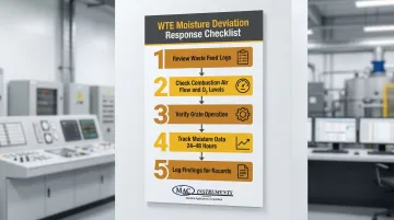
When deviations persist, work through these checks in order:
- Review waste feed logs for composition changes
- Check combustion air flow and O₂ levels against baseline
- Verify grate operation and waste bed depth
- Track moisture data over 24–48 hours to confirm the pattern
- Log findings for operational records
Out-of-Specification Readings (>5% Deviation or Outside Equipment Limits)
High Moisture (>20% or sudden increases >5%):
- Excessive waste moisture (rain-soaked waste, wet season conditions)
- Incomplete combustion (low furnace temperatures)
- Air in-leakage at negative pressure areas
- Measurement system failure or calibration drift
Low Moisture (<10%):
- Insufficient waste moisture (fire risk, dust generation)
- Measurement error or sensor failure
- Sampling location issues (air dilution from leaks)
- Unusually dry waste composition
Out-of-spec readings require a structured response:
- Verify measurement system calibration and sampling integrity first — rule out instrument error before adjusting operations
- Inspect the combustion chamber for air leaks using thermal imaging
- Confirm waste feed moisture with grab samples
- Adjust combustion controls as needed (air flow, grate speed)
- If emission limits are affected, log the incident for compliance reporting
- Contact your analyzer manufacturer for technical support if sensor malfunction is suspected
Common Errors in Measuring Flue Gas Moisture
Measurement accuracy depends on proper technique. The following mistakes lead to false readings and poor operational decisions that compromise both compliance and equipment protection.
Condensation in Sample Lines or Probe
When sample gas temperature drops below the dew point in unheated or inadequately heated sample lines, water drops out and produces falsely low moisture readings. In WTE flue gas, the acid dew point (typically 135°C) runs higher than that of pure water due to SO₃ and HCl content — making this risk more pronounced than in conventional combustion applications.
Prevention: Maintain sample line temperature at 120°C minimum; 191°C is recommended for WTE applications to prevent condensation of both water vapor and acid gases.
Improper Sampling Location
Sampling near bends, dampers, or burners — or in zones where air in-leakage occurs — yields readings that don't represent actual flue gas composition. Stratified flow compounds this problem by creating moisture gradients across the duct cross-section.
Prevention: Sample in straight duct sections with well-mixed flow per EPA Method 1 guidelines: at least 8 diameters downstream and 2 diameters upstream from any flow disturbance.
Failure to Compensate for Temperature and Pressure
Moisture content is temperature- and pressure-dependent. Skipping corrections when comparing readings across different conditions — or when converting between wet and dry basis — introduces systematic calculation errors that compound over time.
Prevention: Record absolute temperature and pressure at the measurement point, then apply EPA Method 4 correction formulas (Eq. 12.1.1) to standardize results before reporting or comparison.
Safety and Best Practices for Flue Gas Moisture Measurement
Working with high-temperature, corrosive WTE flue gas introduces real hazards — for both personnel and instrumentation. Three areas demand consistent attention: personal protective equipment, lockout/tagout procedures, and sample system integrity.
Personal Protective Equipment
- Heat-resistant gloves when handling probes or sample lines
- Safety glasses with side shields
- Respiratory protection if accessing areas with potential flue gas exposure
- Fall protection when working on elevated platforms
Beyond PPE, procedural controls are equally critical during installation and maintenance work.
Lockout/Tagout and Hot Work Permits
- Follow plant LOTO procedures when installing or maintaining measurement equipment on pressurized systems
- Obtain hot work permits for any cutting or welding on flue gas ducts
- Verify flue gas temperature before probe insertion to prevent equipment damage — standard sensors are rated to 1200°F
Proper procedural discipline protects personnel; a well-maintained sample system protects measurement accuracy.
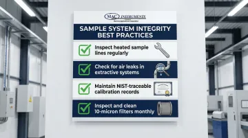
Sample System Integrity
- Regularly inspect heated sample lines for damage and verify temperature controller operation
- Check for leaks in extractive sampling systems, since false air dilutes readings by 10–20%
- Maintain calibration records for compliance documentation (EPA requires NIST-traceable calibration)
- Inspect and clean 10-micron filter elements monthly or install automatic blow-back systems
Conclusion
Accurate flue gas moisture measurement is essential for WTE plant efficiency, emissions compliance, and equipment protection. Moisture levels directly impact combustion efficiency, heat recovery effectiveness, and the risk of acid condensation corrosion in downstream equipment.
Selecting the right measurement method comes down to your plant's requirements for accuracy, response time, and maintenance capacity. Each approach involves real trade-offs:
- Psychrometric methods carry low upfront cost but can't handle high-temperature WTE conditions
- Optical systems respond quickly but demand significant capital investment and ongoing maintenance
- Solid-state sensors, such as MAC Instruments' technology, deliver ±1% full-scale accuracy and reliable performance in harsh environments with minimal maintenance overhead
Getting that measurement right pays off across the board. When operators act on accurate moisture data, combustion runs cleaner, equipment problems surface before they escalate, and plants stay on the right side of EPA requirements under 40 CFR Part 60 Subparts Eb and AAAA.
Frequently Asked Questions
What is the typical moisture content range in waste-to-energy flue gas?
WTE flue gas typically contains 10-25% moisture by volume (wet basis), with municipal solid waste averaging 12-18%. The range depends on waste composition—food waste contributes more moisture than paper or plastic—and combustion efficiency. U.S. facilities commonly report exit gas moisture levels between 10.1% and 19.63%.
How often should flue gas moisture be measured in a WTE plant?
Continuous monitoring is recommended, with data averaged over 1-hour periods per EPA compliance requirements. At minimum, measure during each operating shift and whenever waste composition changes significantly or combustion issues arise.
Can high moisture content in flue gas damage plant equipment?
Yes. Excessive moisture (>20%) reduces combustion efficiency and triggers acid condensation in cooler duct sections when combined with SO₂ and HCl — surface temperatures must stay above 135°C to prevent corrosion. High moisture also reduces heat recovery effectiveness and can impair particulate collection.
What regulations require flue gas moisture monitoring in waste-to-energy plants?
EPA requires moisture measurement for emissions compliance calculations under 40 CFR Part 60 Subpart Eb (large WTE plants) and Subpart AAAA (small WTE plants). Moisture data is used to convert pollutant concentrations from wet basis to dry basis and correct to a standard oxygen level for regulatory comparison.
How does flue gas temperature affect moisture measurement accuracy?
Temperature directly affects moisture measurement in three ways: it determines the gas saturation point, degrades psychrometric sensor accuracy above 200°C, and must be recorded simultaneously for correct moisture calculation. MAC Instruments' solid-state sensors maintain ±1% accuracy at temperatures up to 1200°F.
What is the difference between wet basis and dry basis moisture measurement?
Wet basis expresses moisture as a percentage of total gas volume (including water vapor); dry basis expresses it relative to dry gas volume only. Emissions regulations require dry basis for pollutant concentration reporting — for example, 15% wet basis equals 17.6% dry basis.