Many power plants struggle with moisture measurement challenges: probe condensation at extreme temperatures, calibration drift in corrosive gas streams, and equipment failures that invalidate test results. These issues aren't just operational headaches—they can trigger compliance violations and costly retesting.
This article covers EPA-compliant measurement methods, equipment requirements for temperatures up to 2400°F, interpretation guidelines for typical fuel-specific moisture ranges, and best practices that prevent the most common measurement errors.
Key Takeaways
- EPA Method 4-compliant equipment requires heated probes (≥120°C), ice bath condensers, calibrated dry gas meters (±2%), and temperature/pressure sensors
- Three approaches: Reference Method (compliance), Approximation Method (pre-test estimates), and Continuous CEMS with quarterly validation
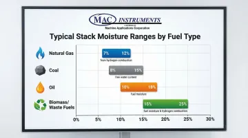
- Typical moisture ranges by fuel: natural gas 7–12%, coal 8–15%, oil 10–18%, biomass 15–25% by volume
- Prevent errors by keeping probes above dewpoint, following Method 1 traverse points, and holding leak rates under 4%
- Use NIST-traceable sensors with automatic temperature compensation and weatherproof construction for stack installations
What You Need to Measure Stack Moisture in High-Temperature Power Plants
Equipment selection for stack moisture measurement must account for three critical factors: stack temperatures reaching 2400°F in some power plants, corrosive combustion gases, and EPA accuracy requirements that leave zero margin for error.
Essential Equipment Components
Heated Probe System
Your probe must maintain temperatures above the stack gas dewpoint—typically 120°C (248°F) minimum—throughout the entire sampling period. If the probe temperature drops below this threshold, moisture condenses before reaching your collection system, causing consistently low readings that invalidate your test.
Construct the probe from stainless steel or borosilicate glass, using either in-stack or heated out-of-stack filtration. The filter protects your condenser system from particulate matter that would otherwise interfere with moisture collection.
Condenser System
The standard configuration uses four impingers in an ice bath maintained below 20°C:
- Impingers 1 & 2: Known volumes of water to capture moisture from the gas stream
- Impinger 3: Empty, to catch carryover between stages
- Impinger 4: Pre-weighed silica gel to capture any residual moisture
This gravimetric setup—measuring the actual mass of collected water—meets EPA Method 4 reporting requirements directly.
Metering System
Your dry gas meter must measure sample volume within 2% accuracy at flow rates of 0.021 m³/min (0.75 cfm) or less. The meter connects to an orifice manometer that maintains constant sampling rate within ±10% throughout the test.
Volume accuracy directly affects your final moisture calculation, so annual calibration to determine the meter's Y-factor correction is mandatory.
Temperature and Pressure Sensors
Calibrated thermocouples must measure within ±1°C accuracy, while barometers require ±2.5 mm Hg precision. These measurements correct your sample volumes to standard conditions (293°K, 760 mm Hg)—a required step before calculating moisture content.
Pre-Sampling Requirements
Traverse Point Determination
EPA Method 1 specifies minimum traverse points based on stack geometry:
- Circular stacks <24" diameter: 8 points minimum
- Rectangular stacks <24" equivalent diameter: 9 points minimum
- Circular stacks >24" diameter: 12 points minimum
- Rectangular stacks >24" equivalent diameter: 12 points minimum
These traverse points must be located at specific percentages of stack diameter to ensure representative sampling across velocity and moisture gradients.
Leak-Check Procedures
Conduct a pre-test leak check at 380 mm Hg vacuum (optional under EPA Method 4, though strongly advised for early leak detection). The mandatory post-test leak check determines whether your sample volume is valid.
Maximum allowable leak rate: 4% of average sampling rate or 0.00057 m³/min (0.020 cfm), whichever is less. Exceeding this threshold voids your test results.
Methods to Measure Stack Moisture Accurately
Method selection depends on three factors: required accuracy (regulatory vs. operational), measurement frequency (periodic vs. continuous), and stack conditions (temperature, pressure, saturation level).
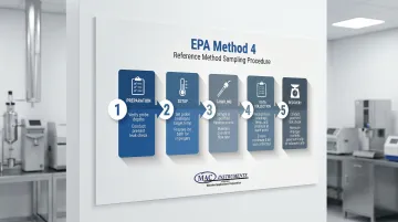
Reference Method (EPA Method 4 - Gravimetric/Volumetric Analysis)
The Reference Method is the gold standard for regulatory compliance. It extracts a gas sample through a heated probe into a condenser system where moisture is captured in impingers and measured by weight and volume.
Equipment Needed
- Complete sampling train with heated probe (120°C minimum)
- Four-impinger condenser system in ice bath
- Silica gel trap (pre-weighed)
- Calibrated dry gas meter with Y-factor
- Vacuum pump capable of maintaining constant flow
- Barometer and temperature sensors
Step-by-Step Procedure
Preparation: Mark probe insertion depths for each traverse point, then conduct a leak check at ≥380 mm Hg vacuum. Transfer known water volumes (typically 100 ml) into the first two impingers and weigh the fourth impinger containing fresh silica gel.
Setup: Heat probe to 120°C and allow temperature to stabilize. Place impingers in ice bath and verify temperature <20°C.
Sampling: Position probe at the first traverse point. Begin sampling at constant rate (typically 0.021 m³/min). Divide total sampling time equally among all traverse points—use a timer or calculate target ΔVm for each point.
Data Collection: Record dry gas meter readings, meter temperature, and barometric pressure at each traverse point. Maintain ice bath temperature throughout sampling by adding ice as needed. Collect minimum 0.60 scm total sample volume.
Recovery: Conduct mandatory post-test leak check. Measure final volume of water in impingers (to nearest 0.5 ml). Weigh silica gel to determine moisture gain.
With sampling complete, apply the following equation to determine moisture content:
Bws = (Vwc(std) + Vwsg(std)) / (Vwc(std) + Vwsg(std) + Vm(std))
Where:
- Vwc(std) = volume of water condensed, corrected to standard conditions
- Vwsg(std) = volume of water captured by silica gel, corrected to standard conditions
- Vm(std) = volume of dry gas metered, corrected to standard conditions
This method is required for regulatory emission testing, compliance demonstrations, CEMS validation, and establishing baseline moisture profiles — including Relative Accuracy Test Audits (RATAs) conducted quarterly. The tradeoff: each test takes 1-2 hours minimum, requires skilled technicians, and cannot support real-time process control.
For situations where full compliance testing isn't required, a simplified approach provides faster estimates with less equipment.
Approximation Method (Quick Moisture Estimation)
A simplified version of the Reference Method using two midget impingers, this approach provides estimates within ±2-3% moisture — sufficient for setting isokinetic sampling rates before full compliance runs.
Equipment Needed
- Heated probe with glass wool filter
- Two 30-ml midget impingers
- Ice bath
- Silica gel drying tube
- Needle valve and diaphragm pump
- Dry gas meter
- Rotameter (0-3 L/min range)
- Vacuum gauge
Step-by-Step Procedure
Place exactly 5 ml water in each impinger. Conduct leak check at 250 mm Hg vacuum with <2% leak rate.
Insert probe at representative stack location. Sample at constant 2 L/min rate until meter reads approximately 30 liters or visible droplets carry over to the second impinger.
Combine impinger contents and measure total volume to nearest 0.5 ml. Record meter temperature and pressure.
Apply this simplified formula to estimate moisture:
Bws = Vwc(std) / (Vwc(std) + Vm(std)) + 0.025
The 0.025 constant assumes 2.5% moisture exits the second impinger uncaptured.
This method works well for pre-test estimates, setting initial sampling parameters, and quick moisture checks during process troubleshooting. Its lower accuracy makes it unacceptable for regulatory calculations unless validated within 1% of the Reference Method.
When process control demands continuous data rather than periodic snapshots, sensor-based monitoring offers a different class of solution.
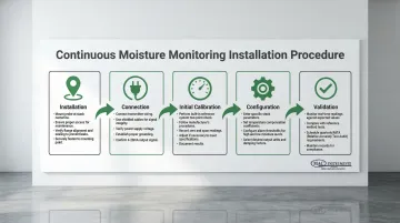
Continuous Monitoring Method (Real-Time Sensor Technology)
Sensor-based systems provide continuous moisture measurement at temperatures up to 2400°F without chemicals, wet bulb techniques, optics, or compressed air. The MAC Instruments MAC155, for example, includes an internal water reservoir for two-point calibration verification and NIST-traceable direct measurement — features developed specifically for high-temperature CEMS environments.
Equipment Needed
- High-temperature moisture analyzer with heated probe assembly
- Weatherproof transmitter enclosure (NEMA 4X rating)
- Temperature compensation circuitry
- Data logging capabilities with 4-20mA or digital output
- Built-in calibration reference system
Step-by-Step Procedure
Installation: Mount probe at representative measurement location — typically stack centerline or per Method 1 guidelines. For power plants, installation takes minutes when using direct-mount configurations.
Connection: Connect probe to transmitter and verify power supply and signal integrity. Configure output scaling for your data acquisition system.
Initial Calibration: Perform calibration check using the built-in reference system. Advanced systems include internal water reservoirs that generate reference humidity levels for two-point calibration verification.
Configuration: Set temperature compensation parameters for your stack conditions. Configure alarm thresholds for out-of-range moisture detection.
Validation: Monitor real-time readings with periodic validation against Reference Method. Quarterly RATAs are required to demonstrate CEMS agreement within ±1% moisture of reference methods.
Output is a direct reading in % moisture by volume with automatic temperature and pressure compensation — no formula required. Response time is 60 seconds or less to reach 90% of final value.
This approach suits continuous emissions monitoring systems (CEMS), process optimization, combustion control, and early detection of moisture-related issues. Real-time adjustments become possible in ways that periodic testing simply cannot support.
The main considerations: initial investment typically runs $15,000-$30,000, and periodic Reference Method validation is required. That said, continuous data regularly surfaces process variations that scheduled testing misses entirely.
How to Interpret Stack Moisture Readings
Moisture content shapes three things: emission calculations (converting dry-basis to wet-basis concentrations), combustion efficiency assessments, and early detection of operational problems when readings drift outside expected ranges.
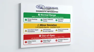
Normal/Acceptable Moisture Ranges
Typical moisture ranges vary by fuel type due to differences in hydrogen content and free water:
- Natural gas: 7-12% moisture (high hydrogen content produces water during combustion)
- Coal: 8-15% moisture (moderate hydrogen, minimal free water)
- Oil: 10-18% moisture (moderate hydrogen content)
- Biomass/waste fuels: 15-25% moisture (significant free water content, highly variable)
Calculate expected moisture using stoichiometric equations: Bws = BH + BA + BF, where BH is moisture from hydrogen in fuel, BA is from ambient air humidity, and BF is from free water in fuel.
Action: If readings fall within expected range (±2% of calculated value), proceed with emission calculations. Use measured moisture to convert dry-basis pollutant concentrations to wet-basis using: Cwet = Cdry × (1 - Bws).
Minor Deviations (2-4% Outside Expected Range)
Possible causes include:
- Changes in fuel composition or moisture content
- Variations in excess air levels (check O₂ readings)
- Ambient humidity fluctuations
- Minor calibration drift in sensors
Work through these investigation steps before proceeding:
- Review current fuel analysis data to verify hydrogen content and moisture specifications
- Compare excess air/O₂ levels against historical data — increased excess air dilutes moisture readings
- Check ambient conditions: temperature, humidity, and barometric pressure
- Confirm equipment calibration dates and look for consistent directional bias
Action: Document the deviation in your test report. Investigate root cause before proceeding with compliance calculations. Consider re-sampling if deviation persists across multiple measurements. Recalibrate equipment if last calibration exceeded 30 days or readings show consistent directional bias.
Significant Out-of-Spec Readings (>4% Deviation or Physically Impossible Values)
Watch for these readings that signal equipment or process problems:
- Moisture >30%: suggests a saturated gas stream or water droplet entrainment
- Moisture <4%: unlikely except in very dry processes with minimal hydrogen fuel
- Sudden changes >5% with no corresponding process modifications
If saturation is suspected, conduct a parallel measurement using the psychrometric method: measure stack temperature at each traverse point using a thermocouple attached to your probe. Calculate saturation moisture from vapor pressure tables at the measured temperature and pressure. Report the lower of the two values — impinger analysis vs. saturation calculation.
Action: Reject test results and investigate equipment issues before repeating the test. Check leak rates, verify probe heating maintained >120°C throughout sampling, confirm condenser temperature stayed <20°C, and inspect for water droplet entrainment. Correct identified problems and repeat measurement.
Using Moisture Data for Emission Calculations
Convert pollutant concentrations from dry basis to wet basis using:
Cwet = Cdry × (1 - Bws)
For example, if your CEMS measures 150 ppm SO₂ on a dry basis and moisture content is 10%:
150 × (1 - 0.10) = 135 ppm SO₂ wet basis
Volumetric flow calculations depend on moisture content as well. Accurate density corrections and mass emission rate determinations — both required under F-factor methodology per EPA Method 19 — cannot be completed without a reliable moisture figure.
Common Errors in Stack Moisture Measurement
Measurement errors directly impact emission calculations, leading to regulatory non-compliance or flawed process control decisions. Knowing where these errors occur is the first step to preventing them.
Inadequate Probe Heating Leading to Moisture Condensation
If probe temperature drops below stack gas dewpoint, moisture condenses in the probe before reaching your condenser system. This causes systematically low moisture readings—by 5% or more.
To avoid this:
- Verify probe maintains ≥120°C throughout sampling
- Inspect for cold spots at joints, bends, and connections
- Use insulated probe sections on long runs
- Monitor probe temperature continuously — a sudden drop points to heating element failure
Improper Traverse Point Selection or Sampling Time Distribution
Sampling only at easily accessible points or spending unequal time at traverse points produces non-representative samples. Moisture stratification in stacks can create 3–5% variations between center and wall locations.
How to prevent this:
- Follow EPA Method 1 point locations exactly — for a 36-inch circular stack, that means 12 points at specific distances from the wall
- Divide total sampling time equally among all traverse points
- Use a timer or calculate target ΔVm (meter volume change) per point to stay on track
Excessive Leak Rates Compromising Sample Volume Accuracy
Leaks after the pump cause the meter to under-register actual sample volume. Leaks before the pump dilute your sample with ambient air (typically 1–2% moisture), causing low readings.
Prevention steps:
- Run mandatory pre-test and post-test leak checks
- Stay within the maximum allowable leak rate: 4% of sampling rate or 0.00057 m³/min, whichever is less
- Focus on common leak sources: impinger connections, probe joints, and pump seals
- Apply vacuum grease to ground-glass joints and verify all connections before each test
Calibration Drift and Failure to Correct for Standard Conditions
Uncalibrated meters, temperature sensors, or barometers introduce systematic errors that compound through your calculations.
Prevention Steps:
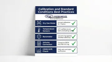
- Calibrate dry gas meter annually to determine Y-factor correction
- Verify temperature sensor accuracy ±1°C using ice bath (0°C) and boiling water (100°C at sea level)
- Check barometer ±2.5 mm Hg against a certified reference
- Always correct volumes to standard conditions (293°K, 760 mm Hg) using measured Tm and Pm values
- Check CEMS zero and span drift daily and adjust if drift exceeds twice the performance specification
Safety and Best Practices for High-Temperature Measurement
Power plant stacks present multiple hazards: extreme temperatures up to 2400°F, elevated work platforms, toxic combustion gases, and high-velocity gas streams capable of pulling equipment into the stack.
Personal Protective Equipment and Access Safety
Required PPE:
- Heat-resistant gloves (rated for 250°F minimum) when handling heated probe components
- Safety glasses with side shields
- Hard hat
- Fall protection when working at elevation per OSHA 1910 Subpart D
Sampling platforms must be stable, properly railed, and rated to support the combined weight of equipment and personnel. Never work alone at elevation — keep communication open with ground personnel throughout testing.
Lockout/Tagout and Hot Work Procedures
Most power plants sample during operation, so process shutdown isn't required. If probe insertion requires opening stack access ports, follow facility hot work permit procedures.
Verify no explosive atmospheres are present before opening any port. Hot work permits require fire watch personnel when combustible materials are within 35 feet — keep fire extinguishers accessible throughout all stack access operations.
Equipment Handling and Maintenance in Extreme Conditions
Handle probes and enclosures with care under extreme conditions:
- Probe cool-down: Wait at least 15–30 minutes after shutting off heaters before disconnecting — probes at 120°C cause instant contact burns. Use insulated gloves even after cool-down.
- Weather protection: Use NEMA 4X-rated enclosures for outdoor continuous monitors; these protect electronics from rain, snow, and temperature extremes.
- Cold-climate operation: Systems with built-in case heaters maintain reliable operation down to -40°F.
Maintenance Intervals
- Maintain ice bath temperature <20°C throughout sampling by adding ice/salt mixture as needed
- Inspect heated probe elements and thermocouples regularly for degradation in high-temperature service
- Clean or replace filter elements when pressure drop increases
- For continuous monitors, verify calibration quarterly using built-in reference systems or Reference Method comparison
Frequently Asked Questions
What is EPA Method 4 and when is it required for power plant stack moisture measurement?
EPA Method 4 is the reference method for determining moisture content in stack gases using gravimetric or volumetric analysis of condensed water. It's required for compliance testing when calculating emission rates, demonstrating CEMS accuracy through quarterly RATAs, and establishing fuel-specific moisture profiles.
How often should stack moisture measurement equipment be calibrated in high-temperature applications?
Dry gas meters require annual calibration to determine the Y-factor correction. Temperature sensors and barometers should be verified quarterly or before each test series. Continuous monitoring systems need quarterly accuracy checks against EPA Method 4 reference measurements — high-temperature environments may require more frequent checks due to sensor degradation from thermal cycling and corrosive gas exposure.
What moisture content accuracy is required for regulatory compliance testing?
EPA Method 4 requires sample volume measurement within 2% accuracy and leak rates <4% of sampling rate. The overall moisture determination should be accurate enough that emission calculations meet applicable relative accuracy requirements—typically ±10-20% of reference method for CEMS. Most regulatory applications require moisture measurement within ±1% absolute moisture content when comparing continuous monitors to reference methods.
Can I use continuous moisture monitoring instead of periodic EPA Method 4 testing?
Continuous monitors meeting CEMS performance specifications in 40 CFR Part 60 can be used for process control and real-time emission calculations. However, periodic EPA Method 4 reference testing is still required for CEMS certification through RATAs every 4-12 months. Continuous systems must demonstrate agreement within ±1% moisture of reference methods.
What should I do if moisture readings indicate saturated conditions or water droplets in the stack?
Measure stack temperature at each traverse point and calculate saturation moisture content using vapor pressure tables. Use the lower value between impinger analysis and saturation calculation as your reported result. If chronic saturation is recurring, consider moisture eliminators or raising stack temperature to resolve the root cause.
Why do different fuels produce different stack moisture content ranges?
Stack moisture comes from three sources: hydrogen combustion, free water in the fuel, and moisture in combustion air. Natural gas produces 7-12% moisture from its high hydrogen content; coal yields 8-15% with minimal free water; biomass and waste fuels contribute 15-25% due to significant free water content. The F-factor method accounts for these fuel-specific differences.
About MAC Instruments
Since 1990, MAC Instruments has built high-temperature moisture analyzers designed for power plant stack emission monitoring. The MAC155 Moisture Analyzer operates at temperatures up to 2400°F with NIST-traceable accuracy and a built-in calibration system that supports EPA compliance requirements. Reach our technical team at 419-621-2322 or info@macinstruments.com.