Introduction: Understanding Moisture Measurement in HRSG Stacks
Many power plant operators struggle with maintaining accurate moisture measurements in HRSG (Heat Recovery Steam Generator) stacks, creating costly compliance gaps and measurable losses in plant profitability. EPA's 2026 New Source Performance Standards mandate continuous compliance monitoring for NOx emissions, requiring precise moisture correction when pollutant and diluent monitors operate on different moisture bases.
HRSG stacks create measurement conditions most sensors aren't built to handle: exhaust gases reaching 600°F (315°C), corrosive acidic compounds, and rapid cycling that causes thermal shock. These factors degrade sensors, accelerate calibration drift, and open measurement gaps precisely when compliance records matter most.
TLDR:
- Accurate moisture data is mandatory for EPA NOx compliance and heat rate calculations
- HRSG exhaust temperatures (250–600°F) and acidic gases rapidly degrade standard sensors
- Cycling operations create thermal shock that accelerates sensor drift and failure
- Traditional wet bulb and optical sensors struggle with contamination and maintenance demands
- Solid-state sensors with built-in calibration offer a more reliable path to continuous, compliant measurement
Why Moisture Measurement Matters in HRSG Stacks
Accurate moisture measurement touches three areas that directly affect plant profitability: regulatory compliance, thermal efficiency, and equipment health. Getting it wrong has consequences in all three.
Regulatory Compliance and Financial Risk
Under 40 CFR Part 75, facilities must apply moisture correction when NOx monitors and diluent sensors (O2/CO2) measure on different moisture bases. Missing or inaccurate moisture data triggers conservative substitute values that artificially inflate reported emissions, potentially triggering compliance violations and penalties.
The 2026 NSPS amendments removed outdated ANSI/ASME PTC 19.10-1981 as an acceptable alternative, reinforcing EPA Method 4 as the reference standard. Facilities can no longer rely on older methodologies; continuous, accurate moisture monitoring that meets current EPA specifications is now required.
Performance Optimization and Efficiency Losses
Moisture content is a fundamental variable in heat rate calculations using the output/loss method. Inaccurate readings mask performance degradation and obscure optimization opportunities.
A documented GE case study found that removing moisture-related deposits (ammonium bisulfate) from an HRSG reduced turbine backpressure by 8 inches water column — yielding roughly $500,000 annually in fuel savings and increased output.
Operational Health Monitoring
Abnormal stack moisture readings serve as early warning indicators for HRSG problems:
- Sudden moisture increases may signal tube leaks or seal failures
- Moisture pattern changes can indicate combustion issues or air infiltration
- Moisture-temperature correlations help identify fouling or flow distribution problems
Integrating moisture data with temperature, pressure, and flow measurements enables operators to validate readings and identify anomalies before they escalate into forced outages.
Key Challenges in Measuring HRSG Stack Moisture
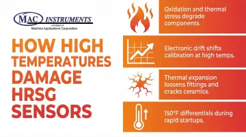
High Temperature Extremes
HRSG exhaust gases typically range from 250°F to 600°F (121°C to 315°C), with supplementary duct burners pushing temperatures higher. F-Class combustion turbines can ramp exhaust temperatures from 1050°F to 1200°F during loading sequences.
Impact on sensors:
- Extreme heat degrades sensor components through oxidation and thermal stress
- Electronic drift accelerates at elevated temperatures, shifting calibration
- Thermal expansion and contraction loosen fittings and crack ceramic elements
- Rapid startups create temperature differentials exceeding 150°F between components
EPA Method 4 requires probes heated to approximately 248°F (120°C) to prevent condensation, adding another layer of thermal management complexity. Sensors must survive both the high stack temperature and their own heating elements operating continuously.
Corrosive Gas Environment
Even natural gas combustion produces corrosive conditions. Trace sulfur compounds form sulfur trioxide (SO3), which raises the acid dew point to approximately 95°C for gas streams with 6.5% water vapor. When stack temperatures fall below this threshold during startup, shutdown, or low-load operation, sulfuric acid condenses on sensor surfaces.
Corrosion mechanisms:
- Acidic condensate (sulfuric and nitric acid) attacks standard sensor materials
- Ammonia slip from SCR systems combines with NOx to form ammonium nitrate deposits
- Particulate matter and ash accumulate on sensor surfaces, creating insulating layers
- Moisture combines with acidic deposits during cool-down, intensifying corrosion
Standard carbon steel and basic stainless alloys suffer stress corrosion cracking in these conditions. Instrumentation requires high-grade stainless steel (316L, 317LMN) or nickel alloys (Hastelloy C276) to survive.
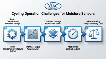
Cycling Operation Impacts
Material selection addresses corrosion in steady-state conditions — but cycling operation introduces a separate category of mechanical stress that even the right alloy can't absorb indefinitely. Modern combined cycle plants increasingly run in cycling modes rather than baseload, introducing severe operational stresses. Research shows tube-to-tube temperature differences reaching 83°C (150°F) during startup, generating substantial thermal stress on intrusive probes.
Cycling challenges:
- Frequent startups and shutdowns create rapid temperature and pressure swings
- Thermal fatigue accumulates with each cycle, accelerating sensor degradation
- Cold ambient starts are especially damaging to pressure parts and sensors
- Calibration drift occurs faster in cycling units than in baseload operations
- Maintaining accuracy across wide operating ranges (cold start to full load) proves difficult
EPRI studies indicate cycling introduces new failure modes and higher damage rates compared to baseload operation, requiring more rigorous inspection and maintenance schedules.
Sensor Technology Limitations
No single sensor technology perfectly addresses HRSG challenges:
Wet bulb psychrometers:
- Require continuous water supply and drainage systems
- Prone to freezing in cold ambient conditions
- Susceptible to fouling from particulates and deposits
- Labor-intensive maintenance and frequent calibration
Optical sensors (chilled mirror hygrometers):
- Offer high accuracy (±0.15°C) as primary measurement standards
- Vulnerable to mirror contamination in dirty gas streams
- Require frequent cleaning in stack applications
- Generally limited to temperatures below 95°C without cooling systems
Capacitive sensors:
- Prone to drift from chemical exposure and aging
- Require periodic recalibration to maintain accuracy
- Secondary measurement nature reduces confidence in harsh environments
- Limited high-temperature capability (typically <200°C)
Calibration and Maintenance Difficulties
Field calibration in harsh HRSG environments presents significant challenges. Many sensors require removal for calibration, causing measurement downtime during critical compliance periods. Without NIST-traceable reference standards on-site, verifying measurement accuracy becomes problematic.
Key compliance and calibration pressures include:
- Daily calibration error tests required under EPA 40 CFR Part 75 for moisture monitoring systems
- Quarterly RATA audits demand documented, traceable measurement accuracy
- Out-of-control data periods triggered by missed or failed calibrations — rendering readings invalid until recalibration is complete
- Permit violations and excess emissions reporting are the direct consequence, not just data gaps
Any lapse in calibration continuity creates regulatory exposure that compounds with each day the system remains out of compliance.
Environmental and Operational Factors Affecting Measurement
Ambient Humidity Variations
EPA Method 4 calculations explicitly account for moisture from ambient air, free water in fuel, and hydrogen in fuel. When ambient humidity shifts, stack moisture readings shift with it — and without careful baseline tracking, operators risk misattributing those changes to process upsets rather than atmospheric conditions.
Supplementary Firing Effects
Duct burners alter temperature and composition profiles in HRSG gas streams. Two problems follow directly from this:
- Flow stratification: Improper distribution of fuel or exhaust gas flow creates temperature gradients and uneven moisture distribution across the duct cross-section.
- Sampling bias: Single-point probes placed in stratified flows capture a non-representative slice of the gas stream, skewing compliance calculations.
Regulatory scope adds another layer. The 2026 NSPS requires combined cycle units with duct burners to measure total NOx downstream of the burner — meaning moisture correction must account for combustion products from both the gas turbine and supplementary firing, not just one source.
Fuel Type Influence
Natural gas combustion produces exhaust with higher moisture content than liquid fuels, driven by methane's high hydrogen-to-carbon ratio. Facilities that switch between fuels must account for these baseline moisture differences in their monitoring strategies.
Solutions for Accurate Moisture Measurement
Advanced Sensor Technologies
Modern moisture analyzers address HRSG challenges through material science and design innovation:
High-temperature materials:
- Ceramic sensor elements withstand extreme temperatures without degradation
- High-grade stainless steel (316L, 317LMN) resists corrosive condensate
- Nickel alloys (Hastelloy C276) provide maximum corrosion resistance
- Heated probe designs prevent condensation on sensing elements
Direct measurement systems:
- Tunable Diode Laser Absorption Spectroscopy (TDLAS) provides non-contact, path-averaged measurement
- Solid-state capacitive sensors eliminate wet bulb techniques and compressed air requirements
- Patented sensor designs respond directly to water vapor pressure without optical components
NIST-Traceable Calibration Systems
Built-in calibration capabilities enable field verification without sensor removal. Advanced analyzers incorporate internal reference gas generation systems that challenge sensors with controlled humidity levels, providing two-point calibration checks that meet EPA requirements.
MAC Instruments' MAC155 operates at temperatures up to 2400°F (1300°C) using patented solid-state sensor technology — no wet bulb, mirrors, optics, or compressed air required. Its built-in calibration system holds enough distilled water (17 fl. oz.) to generate vapor samples for one year of daily calibration checks, meeting EPA regulations without measurement downtime.
Key performance specifications:
- Accuracy: ±1% across all ranges
- Moisture ranges: 3–15%, 6–30%, 9–45%, 12–60% by volume (user-selectable)
- Response time: 60 seconds or less
Protective Housing and Purge Systems
Sensor protection in HRSG environments requires multiple layers of defense:
- 10-micron sintered stainless steel or ceramic filters protect sensors from particulates
- Filter blow-back systems enable automatic cleaning without process interruption
- Heated filter housings prevent condensation that could blind filters
- NEMA 4X/IP53 waterproof enclosures for outdoor installation
- Purge systems protect sensors during plant cleaning operations
- Corrosion-resistant materials throughout all wetted parts
Best Practices for Moisture Monitoring in HRSG Stacks
Reliable moisture monitoring in HRSG stacks depends on consistent protocols across calibration, redundancy, data integration, and maintenance. These four areas directly determine whether your system holds up under both operational variability and regulatory scrutiny.
Calibration Scheduling
- Perform daily calibration error tests as required by 40 CFR Part 75
- Conduct quarterly RATAs comparing system output to reference methods
- Increase calibration frequency for units that cycle daily
- Schedule event-based recertification after sensor replacement or algorithm changes
System Redundancy
- Install redundant moisture sensors for critical compliance monitoring
- Ensure continuous data availability during single-sensor maintenance
- Configure backup systems to activate automatically during primary sensor failures
Redundancy becomes especially important for cycling units, where frequent start-stop cycles accelerate sensor wear and increase the risk of unexpected downtime during monitored periods.
Integrated Monitoring
- Correlate moisture readings with temperature, pressure, and flow data
- Use data validation systems to identify anomalies and outliers
- Track moisture-temperature relationships to detect fouling or stratification
- Implement robust Data Acquisition and Handling Systems (DAHS) for compliance reporting
Maintenance Optimization
- Adapt maintenance schedules for cycling duty rather than calendar intervals
- Monitor sensor drift trends to predict calibration needs
- Stock critical spare parts (filters, sensors, heating elements)
- Document all calibrations and maintenance activities for regulatory audits
Frequently Asked Questions
What does HRSG stand for?
HRSG stands for Heat Recovery Steam Generator — a heat exchanger that captures waste heat from gas turbine exhaust to produce steam. That steam then drives a turbine for additional power or supplies thermal energy to industrial processes.
What are the main components of HRSG?
The main components include the economizer (preheats feedwater using lower-temperature exhaust gas), evaporator (converts water to steam in riser tubes), steam drum (separates saturated steam from water), and superheater (raises steam temperature above saturation for turbine use).
What is HRSG blowdown?
Blowdown is the controlled removal of water from steam drums to prevent dissolved solids from causing scaling and corrosion. Proper blowdown control maintains water chemistry and prevents tube failures that directly affect stack moisture readings.
What is the ramp rate for HRSG?
Ramp rate refers to how quickly an HRSG can increase or decrease steam production, typically measured in MW/min or percentage of rated capacity per minute. Modern F-class units can ramp at approximately 25 MW/min, but thick-walled components like steam drums constrain heating rates to prevent thermal fatigue damage during cycling operations.