Introduction
Moisture control in heat treatment furnaces directly determines whether your parts come out right or end up scrapped. Uncontrolled moisture causes oxidation, decarburization, grain boundary embrittlement, and compromised mechanical properties. Research shows that a dew point increase from -50°C to +5°C in nitrogen-hydrogen atmospheres significantly increases oxide thickness and internal oxidation depth in high-strength steels.
Standard industrial humidity sensors are rated only to 135°C — far below the 850–1000°C operating temperatures typical in carburizing, neutral hardening, and bright annealing. That gap is the core problem. Thermal cycling, corrosive atmospheres, and contamination from soot and oils destroy conventional sensors within days or weeks of direct furnace exposure.
This guide covers how to achieve reliable moisture measurement in heat treatment furnaces — from choosing the right sensor technology to correct installation, calibration, and troubleshooting common failure points.
Key Takeaways
- Standard industrial sensors fail in furnace environments; only sensors rated for continuous operation at 1200°F+ can sustain reliable readings
- Dew point measurement provides the most reliable moisture data, directly correlating to carbon potential and oxidation risk
- Keep sensors away from direct flame zones and use thermal protection with sealed penetrations to prevent premature failure
- Daily or monthly calibration verification using NIST-traceable standards is essential for maintaining accuracy in harsh furnace environments
- Built-in calibration systems and solid-state designs without consumables reduce maintenance demands and extend sensor life
How to Measure Moisture in Heat Treatment Furnaces Without Sensor Failure
Step 1: Select the Right Moisture Measurement Technology
The first critical decision is choosing a sensor technology specifically engineered for high-temperature environments—standard sensors will fail immediately.
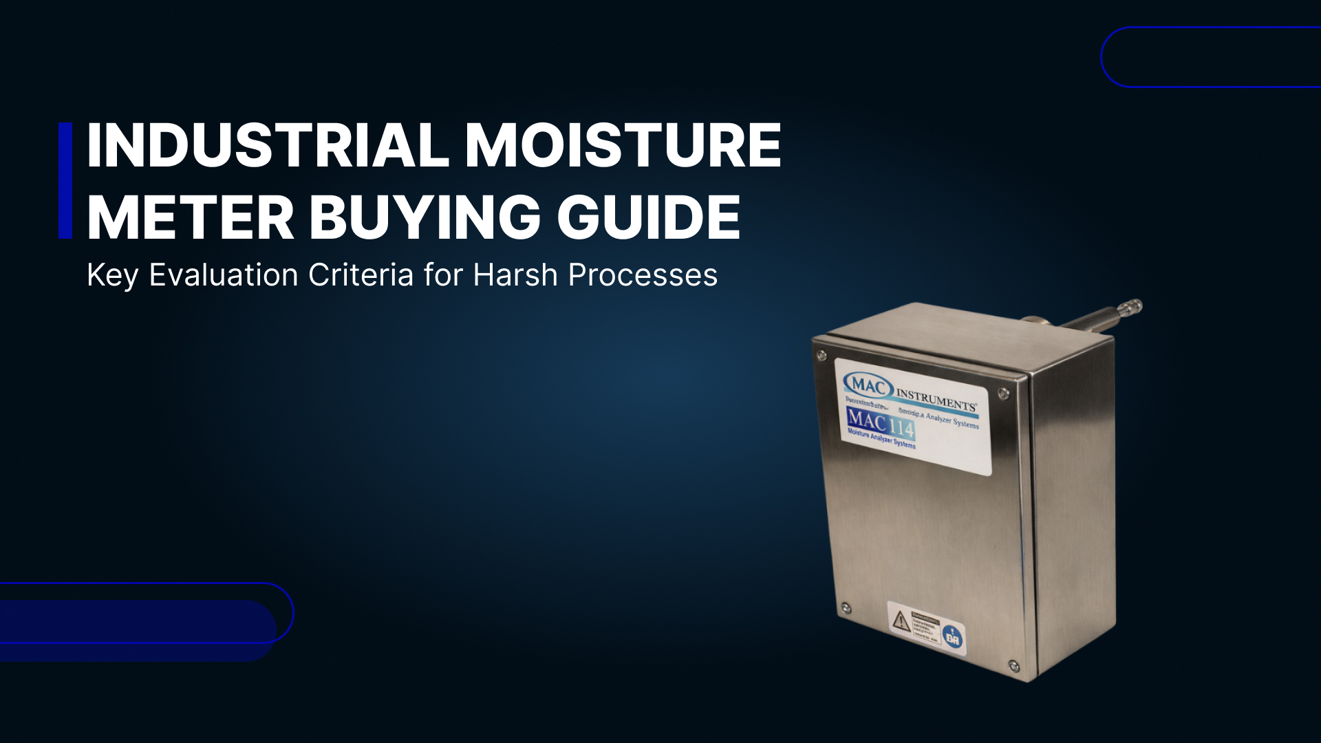
Verify temperature rating matches your furnace conditions. Most industrial humidity sensors operate only to 135°C, while carburizing furnaces run at 850–1000°C. You need sensors rated for continuous operation at your maximum furnace temperature. Specialized high-temperature moisture analyzers like the MAC125 and MAC155 operate continuously up to 1200°F (650°C), with optional capability extending to 2400°F (1300°C) using special mounting hardware.
Evaluate sensor construction for durability. Look for:
- No moving parts that can fail from thermal cycling
- No consumables (chemicals, wet bulbs) requiring frequent replacement
- No optical components (mirrors, lenses) that contaminate or degrade
- Solid-state design that withstands thermal shock
- Weatherproof housings (NEMA 4X or IP66 rated) for harsh environments
Compare measurement technologies:
| Technology | Temperature Capability | Accuracy | Contamination Risk | Best For |
|---|---|---|---|---|
| Aluminum Oxide Sensors | Sampling only (<60°C) | ±2–3°C dew point | Moderate; soot causes drift | General process monitoring |
| Chilled Mirror Hygrometers | Sampling only (<50°C) | ±0.15°C dew point | Low; self-cleaning optics | Laboratory/calibration reference |
| Capacitive Sensors | Sampling only (<180°C) | ±1.8% RH | High; polymer degrades | Ambient applications only |
| High-Temp Proprietary Sensors | Direct to 1200°F+ | ±1% full scale | Low; no fragile components | Furnace direct measurement |

Prioritize NIST-traceable calibration capabilities. Sensors in harsh conditions drift over time. Select instruments with built-in calibration verification or field recalibration capability. The MAC155 includes an onboard calibration system that performs daily two-point verification using an internal water reservoir, so the sensor never needs to come out of service.
Research documented longevity in similar applications. Request case studies or manufacturer data showing sensor performance in comparable furnace environments. Sensors proven across hundreds of installations provide confidence they'll survive your conditions.
Step 2: Determine Optimal Sensor Placement and Installation Location
Strategic placement protects sensors from thermal damage while ensuring representative atmosphere sampling. Get placement wrong and even a perfect sensor gives you bad data.
Follow these placement rules:
- Sample in the circulation path — choose well-mixed zones representative of workload conditions; avoid dead zones with poor flow
- Block direct thermal radiation — keep sensors out of line-of-sight from heating elements, burner flames, or radiant tubes; direct radiation overheats electronics even when surrounding gas temperature is within spec
- Extend probes past the hot face — sampling probes must reach through the furnace wall past the refractory to capture true process atmosphere, not boundary layer gas skewed by wall effects
- Plan for maintenance access — confirm the installation point allows sensor removal and replacement without a full furnace shutdown; keep electronics and connections outside the high-temperature zone
- Never use oxygen probe burn-off ports — soot in those ports releases moisture when heated, producing artificially high readings
- Seal every penetration — air infiltration is the leading cause of false moisture readings; use compression fittings, glands, or welded penetrations to block ambient air entry
Step 3: Install Sensor with Proper Protection and Support Systems
Correct installation with adequate thermal protection determines long-term reliability. Even the right sensor in the wrong installation will fail prematurely.
Thermal protection essentials:
- Insert probes deep enough to reach the measurement zone while keeping the electronics housing outside the extreme temperature area
- Above 1200°F, use special mounting tubes that create a thermal barrier between the measurement point and sensor electronics
- For extreme temperatures, stainless steel probe barrels alone may not be enough — water-cooled or air-cooled probe assemblies protect electronics from conducted heat
Filtration and signal integrity:
- Install 10-micron ceramic or stainless steel sintered filters to block particulate matter; establish a cleaning schedule based on your furnace's soot generation rate
- Shield and ground signal cables away from heating elements, transformers, and high-current conductors
- Use 4-20mA current loop outputs — they resist EMI interference better than voltage signals over long cable runs
Control system integration:
- Connect sensor outputs to data loggers, chart recorders, or process controllers
- Set up moisture trend monitoring and alarms so operators catch air leaks or process upsets early
- For sampling systems, maintain flow rates of 1.5–2.0 SCFH — too low means slow response; too high creates pressure drops that skew readings
Step 4: Establish Calibration and Verification Procedures
Skip calibration in a carburizing furnace and you risk undetected sensor drift that ruins entire parts batches. Build verification into your maintenance schedule from day one.
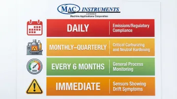
Develop a calibration schedule based on process criticality:
- Critical carburizing/neutral hardening: Monthly to quarterly verification
- Emissions monitoring (regulatory compliance): Daily automated checks using built-in systems
- General process monitoring: Every 6 months
- Sensors showing drift symptoms: Immediate verification
Use appropriate calibration methods:
- Portable chilled mirror hygrometers: Primary standard instruments for field verification—drift-free and NIST-traceable
- Dew point generators: Create precise moisture concentrations for sensor verification
- Built-in calibration systems: Instruments like the MAC155 generate reference humidity levels internally for daily verification without removing the sensor
Document baselines under known conditions. When your furnace atmosphere is stable, sealed, and running at target temperature with correct gas flows, record those moisture readings. Those numbers become your reference point — the difference between "the process changed" and "the sensor drifted."
Train operators to read context, not just numbers. A dew point of +50°F at 1650°F carburizing temperature signals something very different than the same reading at 800°F tempering temperature. Operators need to correlate readings with expected process conditions and recognize when numbers indicate a real problem.
Schedule proactive sensor replacement. Based on manufacturer recommendations and your environment's severity, establish expected service life and replace sensors before in-service failures happen. Keep a spare on hand for critical applications.
When Should You Measure Moisture in Heat Treatment Furnaces?
Moisture measurement isn't universally required—understanding when it's critical versus optional saves unnecessary equipment investment.
Moisture measurement is critical for:
- Carburizing — dew points between +40°F and +60°F control carbon potential (0.8–1.0%) and prevent oxidation at 1650–1750°F. AMS 2759/7 mandates continuous monitoring.
- Neutral hardening — nitrogen-hydrogen atmospheres require dew points of -40°F or lower to prevent decarburization and surface oxidation.
- Bright annealing of stainless steel — ultra-low dew points (-40°F or lower) reduce chromium oxides above 1850°F; silicon oxide reduction may demand -70°F.
Moisture measurement is less critical or impractical for:
- Vacuum furnaces — low-pressure environments contain minimal moisture; vacuum level is the primary control parameter.
- Salt bath operations — molten salt acts as both heat transfer medium and atmosphere, making gas-phase measurement irrelevant.
- Induction hardening — localized, rapid heating leaves no controlled atmosphere to monitor.
- Low-temperature tempering (below 400°F) — oxidation risk is minimal; standard process controls are sufficient.
What You Need Before Measuring Moisture in Heat Treatment Furnaces
Successful moisture measurement requires proper equipment, suitable furnace conditions, and trained personnel.
Equipment and Sensor Requirements
Three categories of equipment form the foundation of any reliable measurement setup:
- High-temperature moisture sensor rated for your maximum operating temperature — 1200°F covers most heat treatment applications, with specialized sensors available for higher ranges. Solid-state designs without consumables, wet bulbs, or optical components hold up best in harsh furnace environments.
- Calibration equipment that is NIST-traceable, either portable reference sensors (chilled mirror hygrometers) for periodic verification or instruments with onboard calibration systems that generate known humidity levels automatically.
- Data acquisition and control systems capable of receiving analog signals (4-20mA or 0-5VDC), displaying real-time readings, trending historical data, and triggering alarms when moisture exceeds acceptable ranges. Integration with furnace controls enables automated carbon potential management.
Furnace Conditions and Atmosphere Quality
Even the best sensor fails quickly in a poorly prepared furnace environment. Before installation, confirm:
- Clean atmosphere — heavy soot, oil carryover, or particulate matter coats sensor surfaces and causes measurement drift or early failure. Resolve upstream contamination sources first.
- Properly sealed furnace — air leaks drive moisture contamination and oxygen ingress more than almost any other variable. Verify door seals, penetrations, and mechanical feedthroughs, then run pressure decay or smoke tests to find leak sources.
- Stable atmosphere flow — fluctuating gas flows, inconsistent endothermic generator output, or variable air additions undermine baseline readings, making it hard to distinguish real process problems from normal variation.
Operator Knowledge and Safety Readiness
Equipment and furnace conditions only get you so far — operator knowledge closes the gap. Training should cover three areas:
- Dew point and carbon potential relationships — operators need to know that dew point readings tie directly to carbon potential through the water-gas shift equilibrium. Lower dew points mean higher carbon potential in endothermic atmospheres; that connection drives corrective decisions.
- Process-specific moisture impacts — whether the process is carburizing, neutral hardening, or bright annealing, operators should know what out-of-range readings mean and what actions to take.
- Safety procedures for high-temperature sensor work — lockout/tagout, hot work permits, and proper PPE are non-negotiable when installing or maintaining sensors on operating furnaces near flammable atmospheres.
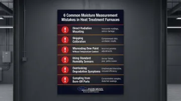
Common Mistakes When Measuring Moisture in Heat Treatment Furnaces
Most sensor failures in heat treatment furnaces trace back to the same preventable mistakes — wrong placement, wrong equipment, or ignored warning signs. Here's what to watch for:
Mounting in direct radiation zones. Sensors with line-of-sight to heating elements, burner flames, or the hot workload absorb radiant heat that exceeds their temperature rating — even when the surrounding gas temperature reads acceptable. Position sensors away from all direct radiation paths.
Skipping calibration verification. Sensors drift in harsh furnace environments. Process adjustments based on drifted readings produce incorrect carbon potential, surface defects, and rejected parts. Set calibration schedules — monthly for critical processes, quarterly at minimum for others.
Misreading dew point without furnace temperature context. A dew point of +50°F means something different at 1400°F than at 1700°F. Operators need to interpret moisture readings relative to current furnace temperature to understand actual carbon potential. Correlation charts or automated control systems handle this reliably.
Using standard humidity sensors. HVAC hygrometers, portable moisture meters, and sensors rated to 200–400°F fail immediately at heat treatment temperatures of 1,400–1,800°F. Only sensors designed specifically for high-temperature furnace environments will survive.
Overlooking early degradation symptoms. Slow response to process changes, readings that don't track known atmosphere conditions, values pinned at range limits, or erratic fluctuations all signal sensor trouble. Don't keep operating on questionable data — investigate immediately.
Sampling from oxygen probe burn-off ports. Soot accumulates in these ports and releases moisture when heated during burn-off cycles, producing falsely elevated readings. Use dedicated sampling ports positioned in clean atmosphere circulation paths.
Troubleshooting Moisture Measurement Issues in Heat Treatment Furnaces
Most moisture measurement problems in heat treatment furnaces fall into three categories: readings that run too high, readings that are erratic or unresponsive, and readings that run suspiciously low. The diagnostic steps below address each scenario directly.
Why Are Moisture Readings Higher Than Expected?
Likely causes:
- Air infiltration through damaged door seals, leaking gaskets, or furnace penetrations
- Water vapor from incoming parts carrying cutting fluids, oils, or residual wash water
- Pinhole leaks in water-cooled components (radiant tubes, fans) that open at high temperatures
- High ambient humidity being drawn into the furnace through leaks
Diagnostic steps:
- Conduct pressure decay testing to quantify leak rate
- Perform soap bubble tests on all penetrations, seals, and mechanical feedthroughs
- Verify parts are properly cleaned and dried before loading
- Check water-cooled components for leaks (often only apparent at operating temperature)
- Add refrigerated dryers to the atmosphere supply when ambient humidity runs consistently high
Why Are Sensor Readings Erratic or Unresponsive to Process Changes?
Likely causes:
- Sensor contamination from soot, oil, or furnace atmosphere deposits coating the sensing element
- Sensor electronics damaged by excessive conducted heat through the probe
- Loose electrical connections or electromagnetic interference from nearby equipment
- Moisture condensation in sample lines (for sampling systems)
Diagnostic steps:
- Remove and visually inspect the sensor for contamination or physical damage
- Clean the sensor per manufacturer instructions (typically involves replacing or cleaning the filter element)
- Verify that sensor mounting provides adequate thermal protection—check if electronics housing is excessively hot
- Inspect electrical connections for corrosion, looseness, or damage
- Reroute signal cables away from heating elements, transformers, and high-current conductors
- For sampling systems, verify heated sample lines are maintaining temperature above dew point to prevent condensation
Why Are Moisture Readings Lower Than Expected or Showing "Out of Range" Errors?
Likely causes:
- Sensor positioned in a dead zone with poor atmosphere circulation
- Sensor has drifted out of calibration (particularly aluminum oxide sensors)
- Atmosphere being over-dried by excessive nitrogen purging or air dilution
- Sample line flow rate too low (for sampling systems)
Diagnostic steps:
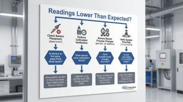
- Verify sensor placement allows representative sampling—relocate if in a dead zone
- Perform calibration verification using a NIST-traceable portable reference sensor or dew point generator
- Review recent process changes: altered gas flow rates, increased air additions, or modified burnout procedures
- For sampling systems, verify flow rate is 1.5–2.0 SCFH—increase if below minimum
- Cross-check with shim stock analysis: process a carbon test coupon
- Verify that actual carbon content matches what the moisture readings predict
Frequently Asked Questions
Why is my heat treatment furnace producing condensation and raising indoor humidity?
Condensation occurs when moisture desorbs from heated parts into the furnace atmosphere. If the furnace atmosphere isn't properly ventilated or if door seals and penetrations are leaking, this moisture escapes into the plant environment where it condenses on cooler surfaces like walls, ductwork, and equipment. Fix leaking furnace seals and ensure proper atmosphere exhaust ventilation.
What is the dew point in heat treatment?
Dew point is the temperature at which water vapor in the furnace atmosphere condenses into liquid water. In heat treatment, it's the primary measurement of moisture content because it ties directly to carbon potential (through the water-gas shift reaction) and surface oxidation risk. Lower dew points indicate drier atmospheres with higher carbon potential.
How often should moisture sensors in heat treatment furnaces be calibrated?
Calibrate monthly to quarterly for carburizing and neutral hardening processes. Emissions monitoring applications with regulatory requirements benefit from daily automated verification, such as the built-in calibration system in the MAC155. Increase frequency if sensors show drift or operate in heavily contaminated environments.
Can I use a standard humidity sensor in my heat treatment furnace?
No. Standard HVAC or industrial humidity sensors are rated only to 200-400°F and fail immediately in heat treatment furnaces operating at 1400-1800°F. You must use specialized high-temperature moisture sensors with proprietary designs rated for continuous operation at 1200°F or higher, such as the MAC125 or MAC155 moisture analyzers.
What moisture level should I maintain in my carburizing furnace atmosphere?
Target dew points between +40°F and +60°F at carburizing temperatures (1650-1750°F) to achieve 0.8-1.0% carbon potential while limiting oxidation. Exact targets vary with endothermic gas composition, so reference carbon potential correlation charts for your specific atmosphere.
How do I know if my moisture sensor has failed or is giving inaccurate readings?
Warning signs include stuck readings, slow response, erratic fluctuations, or values that don't track with stable process conditions. To verify accuracy, perform shim stock analysis or cross-check with a portable calibrated reference sensor against your installed unit.