Introduction
Moisture in process gas is one of the most damaging variables in chemical reactor operations. Even trace amounts can set off a chain of problems:
- Corrosion that shortens equipment lifespan
- Catalyst poisoning that reduces reaction efficiency
- Unwanted side reactions that compromise product quality
- Equipment damage that leads to costly unplanned downtime
The thresholds are unforgiving. In catalytic reforming, moisture levels as low as 1–3 ppmw can attenuate metal function, decreasing hydrogen production and accelerating coke formation. In ethylene polymerization, Ziegler-Natta catalysts require moisture below 1 ppm to maintain efficiency.
This article covers measurement methods, interpretation guidelines, and best practices specific to chemical reactor environments, helping you select the right technology and implement reliable monitoring systems.
Key Takeaways
- Moisture causes catalyst deactivation, corrosion, and process inefficiencies in reactor systems
- Analyzer selection hinges on operating temperature, required accuracy, and gas composition
- Reactors above 400°F need analyzers built specifically for high-temperature service
- Proper sampling design and regular calibration ensure accurate, reliable measurements
- Understanding your readings helps distinguish false alarms from genuine moisture excursions before damage occurs
What You Need to Measure Moisture in Chemical Reactor Process Gas
Chemical reactors operate under varying temperatures, pressures, and gas compositions, each requiring specific measurement approaches. The right equipment depends on your process conditions and monitoring objectives.
Measurement Technologies and Equipment
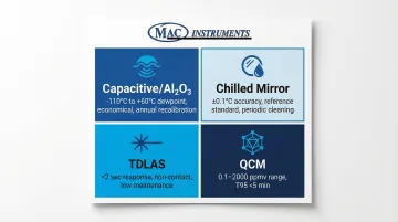
Four primary technologies dominate reactor moisture measurement:
Capacitive/impedance sensors (aluminum oxide or ceramic) measure changes in capacitance as water molecules adsorb into a hygroscopic layer — economical, versatile, and covering wide ranges from -110°C to +60°C dewpoint.
Chilled mirror hygrometers cool a mirror surface until condensation forms. Fundamental accuracy of ±0.1°C and excellent long-term stability make them the preferred choice for reference applications and calibration verification.
Tunable diode laser absorption spectroscopy (TDLAS) measures water molecule absorption at specific laser wavelengths. No contact with the process gas, fast response under 2 seconds, and accuracy of ±1 ppmv or ±3% of reading.
Quartz crystal microbalance (QCM) detects frequency changes in a hygroscopic-coated crystal as it adsorbs water vapor — response under 5 minutes, suited to trace moisture applications from 0.1 to 2000 ppmv.
Technology selection comes down to temperature range, required accuracy, and gas composition — and your choice directly shapes how the sampling system needs to be configured.
Sampling System Components
Essential components include:
- Inlet/outlet valves — isolate the analyzer during maintenance without interrupting reactor operation
- Filtration — removes particulates and contaminants before they reach the sensor (typically 10–100 micron sintered stainless steel)
- Sample conditioning — regulates pressure and temperature to keep samples within analyzer specifications
- Sample probe or block — engineered to minimize moisture adsorption and desorption at wetted surfaces
- Anti-diffusion measures — eliminate dead legs and use electropolished tubing to prevent moisture retention
- Proper venting — maintains safe, representative sample flow through the system
The sampling system must deliver clean, uncontaminated gas to the analyzer without introducing measurement lag. Unheated 316L stainless steel tubing may require heating to 350°C to fully prevent adsorption effects on the tubing walls.
Installation Requirements
Before installation, verify:
- Safe reactor access points that provide representative gas samples
- Proper mounting locations avoiding dead legs and condensation zones
- Temperature and pressure compatibility with analyzer specifications
- Electrical classification compliance (Class I Div 1/2, ATEX, IECEx) for hazardous areas
- Integration points with DCS or control systems (typically 4-20mA signals)
Methods to Measure Moisture in Chemical Reactor Process Gas
Different reactor conditions and accuracy requirements dictate which measurement method is most appropriate for your application.
Method 1: Capacitive/Impedance Sensors (Aluminum Oxide or Ceramic)
An aluminum oxide layer absorbs water vapor, changing the electrical impedance between two electrodes. The result is a dewpoint or ppm output from a capacitive moisture transmitter — economical, pressure-capable, and widely deployed.
Equipment needed:
- Capacitive moisture transmitter
- Sample conditioning system with filtration
- Temperature compensation hardware
Measurement process:
- Install sensor in conditioned sample stream
- Allow equilibration time (transitioning from dry to wet can be slow)
- Read dewpoint or ppm output from transmitter
- Apply temperature and pressure corrections based on process conditions
Performance considerations:
Wide measurement range (−110°C to +60°C dewpoint) and pressure capability up to 345 bar make these sensors versatile. Sensors drift approximately 2°C per year, so annual recalibration is standard practice. Response time is fast for wet-up (under 5 seconds) but slow for dry-down — hours to days in some cases. Contaminants like glycol or oil can affect accuracy.
Method 2: Chilled Mirror Hygrometer (Optical Dewpoint)
This technique cools a mirror surface until condensation forms, then uses a precision platinum resistance thermometer to measure dewpoint directly. It's the reference standard for traceable moisture measurement.
Equipment needed:
- Chilled mirror analyzer with thermoelectric or cryogenic cooler
- Optical detection system for condensation
- Sample system delivering clean, filtered gas
Measurement process:
- Sample gas flows across the mirror surface
- Mirror temperature is controlled to maintain the dew/frost point
- Optical detector identifies condensation formation
- Platinum resistance thermometer provides a direct temperature reading
Performance considerations:
Accuracy of ±0.1°C with no long-term drift makes this the preferred choice for calibration and reference applications. That said, higher cost and periodic mirror cleaning limit its use in continuous dirty-process streams. Glycol contamination can render the technique unsuitable.
Method 3: Tunable Diode Laser Absorption Spectroscopy (TDLAS)
Laser light at a specific water absorption wavelength passes through the gas sample. The absorbed light correlates directly to moisture concentration via the Beer-Lambert Law — no contact with the process gas required.
Equipment needed:
- TDLAS analyzer with laser source and detector
- Optical measurement cell
- Temperature and pressure sensors for compensation
Measurement process:
- Gas flows through the optical measurement cell
- Laser sweeps across the water absorption line
- Measure light absorption using 2F peak detection
- Calculate moisture concentration in ppm or dewpoint
Performance considerations:
Response time under 2 seconds optically, under 5 minutes system-wide, with accuracy of ±1 ppmv or ±3% of reading and no drift. Non-contact measurement is immune to glycol, methanol, and amines. Higher upfront cost is offset by low maintenance, making TDLAS well-suited for closed-loop process control where response time drives yield.
Method 4: Quartz Crystal Microbalance (QCM)
A hygroscopic polymer coating on a quartz crystal adsorbs water vapor, shifting the crystal's resonant frequency in proportion to moisture content. Because the sensor responds to moisture flux rather than steady-state concentration, response is fast.
Equipment needed:
- QCM analyzer with zero gas supply
- Internal moisture generator for calibration verification
- Sample conditioning system
Measurement process:
- Analyzer alternates between process gas and zero gas reference
- Frequency shift indicates moisture level
- Internal moisture generator verifies calibration
- Output displays moisture in ppm or dewpoint
Performance considerations:
T95 response under 5 minutes with accuracy of ±0.1 ppmv or ±10% of reading across 0.1–2,000 ppmv. Requires periodic re-zeroing and clean sample gas. Ethylene glycol can cause downward drift, so sample conditioning is critical in glycol-containing streams.
Comparing the Four Methods at a Glance
| Method | Accuracy | Response Time | Maintenance | Best Use Case |
|---|---|---|---|---|
| Capacitive / Al₂O₃ | ±2°C dewpoint | Fast wet-up; slow dry-down | Annual recalibration | General process monitoring |
| Chilled Mirror | ±0.1°C | Moderate | Periodic mirror cleaning | Reference / calibration |
| TDLAS | ±1 ppmv or ±3% | <2 sec optical | Low | Real-time process control |
| QCM | ±0.1 ppmv or ±10% | T95 <5 min | Re-zeroing required | Trace moisture (ppmv range) |
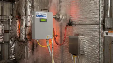
High-Temperature Reactor Applications (Above 400°F / 200°C)
Standard moisture sensors — capacitive, optical, or laser-based — are not built for sustained exposure above roughly 200°C. These applications require specialized high-temperature analyzers or remote sampling with controlled cooling.
MAC Instruments manufactures moisture analyzers rated for continuous operation up to 1,200°F (650°C), with an optional configuration to 2,400°F (1,300°C). The analyzers use a patented solid-state sensor that measures moisture in-situ — directly inside furnaces, calciners, kilns, and reactors — without optics, chemicals, wet bulb techniques, or compressed air. NIST-traceable accuracy is maintained even in environments where conventional sensors would fail within hours.
How to Interpret the Results
Moisture readings must be evaluated against process specifications, reactor operating conditions, and potential impacts on catalyst activity and product quality.
Normal/Acceptable Readings
Acceptable moisture levels vary dramatically based on reactor type and process requirements:
Catalyst protection applications:
- Ethylene polymerization: <1 ppm (some specifications require <0.1 ppm)
- Catalytic reforming feed: 1-3 ppmw
- Catalytic reforming recycle gas: 15-20 ppmv (not exceeding 30 ppmv)
Industry-standard limits:
- Natural gas pipeline quality: <7 lbs/MMscf (approximately 150 ppmv)
- Cryogenic recovery feed: <100 ppbv to prevent freezing
When comparing readings across units, convert between dewpoint (°C/°F), ppm, lbs/MMscf, and g/m³ using standard formulas. Pressure corrections matter: increasing pressure raises dewpoint (appears wetter), while decreasing pressure lowers dewpoint (appears drier), even though moisture concentration in ppm stays constant.
Minor Deviations
Slight upward trends or readings approaching upper specification limits warrant attention:
- Increase monitoring frequency to identify patterns
- Check desiccant dryer performance and regeneration cycles
- Inspect for minor leaks or ambient air infiltration
- Consider seasonal temperature/humidity changes affecting readings
Left unaddressed, minor deviations commonly escalate to desiccant saturation or catalyst exposure within days to weeks depending on process flow rates.
Out-of-Spec Conditions
Readings exceeding specifications require immediate action:
Immediate checks:
- Verify dryer operation and desiccant condition
- Inspect for water ingress points
- Confirm sampling system integrity
Risks of continued operation:
- Catalyst deactivation (often irreversible)
- Corrosion initiation in downstream equipment
- Unwanted side reactions reducing product quality
- Hydrate formation clogging lines and equipment
Isolate affected sections, investigate root cause, and implement corrective action before resuming normal operation.
Common Errors in Measuring Moisture in Reactor Process Gas
Measurement errors can lead to false alarms or undetected moisture problems, both of which compromise reactor safety and efficiency.
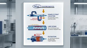
Sampling System Issues
Three sampling system problems account for the majority of field measurement failures:
- Sample point location: Points in dead legs or condensation-prone areas return unrepresentative readings. Sample from well-mixed zones with active flow, avoiding low points where condensate accumulates.
- Line sizing: Small diameter tubing (1/8" OD) with short run lengths minimize internal surface area and residence time, reducing adsorption and lag.
- Filtration: Particulates and liquid droplets reaching sensors cause fouling and erroneous readings. Use sintered stainless steel filters (10–100 micron) with regular inspection intervals.
Insufficient Equilibration Time
Taking readings before sensors fully equilibrate leads to errors, especially after reactor startup or process changes. Aluminum oxide sensors respond quickly to wetting (<5 seconds) but slowly to drying — recovery can take hours to days.
Complex systems can take days to dry down from atmospheric levels to a -60°C dewpoint. Plan scheduled stabilization windows after any major process change before treating readings as valid.
Incorrect Pressure/Temperature Compensation
Failing to apply proper corrections when reactor pressure or temperature differs from calibration conditions creates significant measurement errors. A gas at 1000 ppmv water, for example, has a much higher dewpoint at 200 psig than at atmospheric pressure — the same concentration reads differently depending on where and how it's measured.
To avoid misinterpretation:
- Measure actual gas temperature at the sensor location, not at a remote point
- Specify clearly whether you're reporting process dewpoint (at operating pressure) or atmospheric dewpoint
- Document calibration conditions so operators can apply consistent corrections
Safety and Best Practices
Chemical reactors often contain flammable, toxic, or corrosive gases requiring specific safety measures for moisture measurement systems.
Process Isolation and Hazardous Area Classification
Ensure moisture analyzers and sampling systems comply with area electrical classification. Equipment must meet Class I Div 1/2 (North America) or ATEX/IECEx (international) certifications appropriate for the hazardous zone.
Use proper isolation valves and purge procedures before maintenance. Power must be isolated and systems de-pressurized before opening flameproof enclosures.
With isolation and classification requirements addressed, sample system design is the next critical control point for accurate, safe measurement.
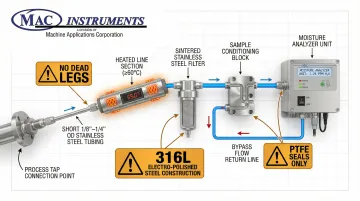
Sample System Design
Reducing lag time, eliminating contamination paths, and selecting compatible materials all directly affect measurement reliability. Key design requirements:
- Short sample lines with small-diameter tubing (1/8" to 1/4" OD) to minimize dead volume
- Heated lines when needed to prevent condensation — maintain above 60°C or at least 10°C above the highest expected dewpoint
- No dead legs — stagnant sections trap moisture and release it slowly back into the sample stream, producing erroneous readings
- Bypass flow to increase volumetric flow rate from process to analyzer and improve response time
- Compatible wetted materials: 316L stainless steel (electro-polished for low-ppm applications), PTFE seals — avoid copper, aluminum, carbon steel, and permeable plastics
Calibration and Maintenance
Establish regular calibration schedules:
- Capacitive sensors: 6-12 months due to drift
- TDLAS and chilled mirror: 1-2 years or longer
- Harsh reactor environments may require more frequent calibration
During maintenance, follow these procedures to prevent contamination and maintain measurement accuracy:
- Use NIST-traceable calibration standards to meet regulatory requirements
- Plug all ports to block atmospheric moisture from entering the system
- Purge sample systems thoroughly with dry nitrogen before reconnecting analyzers
Conclusion
Accurate moisture measurement in chemical reactor process gas protects catalysts, prevents corrosion, and maintains product quality. Success comes down to matching the right technology to your temperature range, accuracy requirements, and process conditions:
- Capacitive sensors — economical wide-range monitoring
- Chilled mirror hygrometers — reference-grade accuracy
- TDLAS — fast, non-contact measurement
- QCM — trace moisture detection at ppm levels
Sampling system design is equally critical. Representative, timely measurements depend on:
- Short tubing runs with small-diameter lines
- Heated sample lines to prevent condensation
- Elimination of dead legs and moisture traps
- Regular calibration against NIST-traceable standards
Correct interpretation of those results is what turns data into proactive process management.
For high-temperature reactors above 400°F — where many standard sensors fail — purpose-built analyzers capable of operating at 1,200°F or higher are the only reliable option. Get the technology, sampling design, and calibration right, and moisture control stops being a reactive problem and becomes a stable part of normal operations.
Frequently Asked Questions
What is a normal reading for a moisture meter in chemical reactor applications?
"Normal" depends on your specific process and catalyst requirements. Many catalytic reactors require <10 ppm moisture, while some processes tolerate 50-100 ppm. Always reference your process specifications and catalyst manufacturer guidelines.
What is the ASTM standard for moisture analyzer calibration?
ASTM D1142 covers manual chilled mirror dew point apparatus, while ASTM D7904 addresses TDLAS measurement of H₂O in natural gas. The key requirement is NIST-traceable calibration regardless of which standard applies to your analyzer.
Can standard moisture analyzers measure process gas above 400°F?
Most standard sensors are limited to <200°F — specialized analyzers or remote sampling with controlled cooling are required above that threshold. MAC Instruments offers analyzers rated to 1200°F (650°C), with optional capability to 2400°F (1300°C) for extreme reactor environments.
How often should moisture analyzers in reactor service be calibrated?
Capacitive/impedance sensors typically need annual calibration due to drift. TDLAS and chilled mirror systems are more stable (1-2 years or longer). Harsh reactor environments may require more frequent calibration. Always follow manufacturer recommendations and regulatory requirements.
What causes slow response time in moisture measurements?
Water molecules adhere to surfaces (adsorption), creating measurement lag. Long sample lines, large-diameter tubing, and wet-to-dry transitions all slow response significantly. Heated lines, short paths, small-diameter tubing, and bypass flow reduce surface area and improve response time.
Why do moisture readings change when reactor pressure changes?
Dewpoint temperature is pressure-dependent. Increasing pressure raises the partial pressure of water vapor, thus raising the dewpoint (appears wetter). Decreasing pressure lowers dewpoint (appears drier). Moisture concentration in ppm remains constant, but dewpoint changes. Always specify whether you're reporting atmospheric or process dewpoint to avoid confusion.